Choose Internal Rendering Engine from the Engine drop-down menu in the PhotoRendering Settings dialog box (Document > Creative Imaging > PhotoRendering Settings). The controls below concern the internal ArchiCAD rendering engine.
Note: The speed of PhotoRendering is defined most of all by image size, while model complexity affects speed if shadows are used. The PhotoRendering effects define the final quality or character of your rendering.
Internal Rendering Engine Effects Panel
Use the controls in this section to select the PhotoRendering effects you want to use:
The Method setting determines how closely the program should adhere to its ultimate imaging capacity.
With the Best button selected, the program calculates the light attributes of each pixel. As the choices decrease in quality, ArchiCAD calculates individual values for every second or third pixel only. The quality increase will affect curved surfaces more than others.
Using multiple light sources or picture mapping may require the Final or Best settings.
The Flat Shading button results in each shape being roughly approximated by flat surfaces only. Special effects like Transparency, Fog, Emission, Smooth Surfaces, Highlights and Light Decay are unavailable. The Flat Shading option is faster than all the other options in this dialog box, but slower than when 3D Window Settings is set to use Shaded mode.
The contour quality of your renderings is controlled by the Antialiasing settings. Jaggedness of the contour is gradually eliminated as you move from Off to Best.
You may want to use the Best option only for final documents, since processing time increases along with quality.
The series of checkboxes in the Effects section lets you enable a variety of light and surface effects, some of which are initially set in the Options > Element Attributes > Surfaces dialog box.
For more information, see Surface Settings Dialog Box.
Specular reflections are taken into consideration and displayed as highlights in your PhotoRenderings when this box is checked.
Note: If Highlights is unchecked, or the Flat Shading method is used, specular reflections are ignored in the rendering.
Check the Emission option if you have chosen, or created, light emitting Surfaces and want this quality to be displayed in the renderings.
Check the Fog option if you have set fog color and intensity in the Sun dialog box (accessible from View > 3D View Options > 3D Projection Settings) and wish to use it in your PhotoRendering.
For more information, see 3D Projection Settings.
Transparency: Transparent elements (such as glass) will be rendered as transparent. (If you leave this box unchecked, such elements will be shown as opaque.)
The degree of smoothing is set through the Smooth Surfaces control, with up to one pixel accuracy. Curved surfaces, which are normally approximated by flat planes, are represented by more lifelike surfaces when this option is on.
If Lamp Falloff is not checked, the angle falloff and distance falloff values in the GDL Scripts of Lamps will be handled as being zero. This results in a sharp border between illuminated and dark areas. If it is checked, the values originally given will be used, resulting in a smooth transition between illuminated and dark areas.
Note: Lamps must be enabled at the Light Sources checkboxes for falloff to operate.
If the Textures box is checked, bitmapped pictures referred to in the GDL script of some library parts will appear on the corresponding surfaces.
It also controls whether the textures linked to surfaces in the Surfaces dialog box are displayed in PhotoRenderings as described.
For more information, see Surface Settings Dialog Box.
You can select which Light Sources (Sun, Lamps or both) you want to use to illuminate the model during the PhotoRendering process. You should select at least one of the two choices.
The Lamps checkbox can only be effective if Lamp type library parts have been placed on the plan. They must be switched on in their Settings dialog box.
In the Shadow Casting section, you can define which of the available light sources you want to cast shadows in the PhotoRendered picture. Check the High Accuracy box if you notice incorrect results on your PhotoRendered picture, especially missing shadows of relatively small elements. This may occur if you zoom in on a small detail of an otherwise large project in the 3D Window and make a photorendering of that detail.
•If the Use transparency checkbox is checked, ArchiCAD will create different shadows for surfaces with different transparency. The color of the transparent surface will also affect the color of the shadow in the final photorendering. This is also valid for surfaces with Alpha channel, where the Alpha channel is used to define the transparency of the surface.
•Use the slider next to the Texture antialiasing checkbox to set the desired image quality. As this procedure is very time consuming, use it only if you require a superior image quality for printing.
Internal Rendering Engine Background Panel
This panel of PhotoRendering Settings is identical for all PhotoRendering engines.
In this panel of the dialog box you can set the attributes of the background for your rendered 3D model.
If the Colors radio button is checked, you can set the color of the sky and the ground in the Set Color subdialog box after clicking the Sky Color or Ground Color button. During the photorendering process ArchiCAD will automatically locate the horizon line of the background to correspond with the horizon of the picture.
In parallel projections, if the bottom of the elements is visible, sky color is used; if not, ground color is used. The 3D Window can also use the colors specified here. If you just need a plain, single color background, click the Chain icon next to the Preview Window and set either the Sky Color or the Ground Color by pushing their button.
ArchiCAD PhotoRendering supports precise horizontal and vertical pixel size and dots per inch resolution. This makes it possible to merge background bitmap images of known proportions and resolutions with PhotoRendering images.
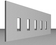
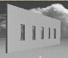
You can make a powerful graphic statement by placing a rendered model against an existing picture as the background. Just turn on the Picture radio button and search for the appropriate picture from the directory dialog box. If you want a different picture for the background, click the Change Picture button. In the Load Image from Library dialog box you can select another picture. Your rendered model will be merged into the background picture in an intelligent manner, masking it when necessary as shown below.
Note: You can save the background picture together with your Project. Use the Save As command to save the project in archive format, then check the Include Background Picture checkbox in the dialog box.
The background picture you selected is fitted into the Preview Window of the dialog box, and you can rescale it with the Resolution and Magnification settings.
The size of the picture will change in the Preview Window, and you can check its real size with the values written above the horizontal line on the right side of the dialog box. (You can also get a sense of how its size is changing by comparing it to the image frame, discussed below, which grows and shrinks as you change these settings.)
If the Show Preview radio button is set to Picture, the Preview Window will show you the whole opened picture, and a bold frame inside it represents the dimensions of your rendered image. You can drag this by clicking inside the frame.
If the bold frame is not visible, it is too large. Just click in the picture and you will see the bold frame. In this case, change either the magnification, the resolution or the image size values to bring the ratio of the incoming and outgoing image sizes closer. Ideally the frame is smaller than the background picture so that you can choose the best detail. If the Image radio button is selected, you will see only the framed part of the background in the Preview Window. You can select another part of the background picture here by clicking the Preview Window and dragging the frame on top of the background picture.
The Use Alpha Channel for Transparency checkbox will allow you to use the Alpha Channel information of the opened background picture if it has any. White color of the Alpha Channel will make the background picture dominant, while black color of the Alpha Channel will make the photorendered image of ArchiCAD dominant over the background.
Internal Rendering Engine Brightness Panel
This panel of the dialog box gives you choices regarding exposure.
Use the dimmer switch to set the desired brightness from dark to bright.
You have three options for correcting possible Overexposures. (Overexposure occurs when the computational method results in a brighter color requirement than the brightest white on the monitor.)
•ArchiCAD can make all surfaces darker than their computed color and make the brightest color white. This keeps the contrast between bright and dark parts of the image, but details in darker areas may be lost.
•You can choose to darken only the overexposed surfaces. This way, dark areas will not be extremely dark, but the contrast between shades in bright areas will be smaller.
•Paint the overexposed surfaces with the selected color to show their place in the picture. This is an editing tool that helps you fine-tune the lighting of your renderings by changing elements of the model (e.g., relocating or dimming individual lamps) rather than applying one of the overall corrections described above.
When you click the Apply button, ArchiCAD will create a new image from the latest PhotoRendered image using the brightness and overexposure correction settings in the dialog box. Creating this new image will take much less time.
Internal Rendering Engine Partial Rendering Panel
This part of the PhotoRendering Settings dialog box provides you with the option of making partial Renderings.
The Partial Rendering settings allow you to specify a range of lines and columns to be rendered for your image. This is useful when you do not want to waste time rendering the entire image.
This method can also be useful for comparing different surface or light conditions within a single image. Additionally, it can be used for continuing images which were stopped when being processed. (You must save the half-completed image and open it as a background picture).
Use this method if you make a modification in the model that affects only the unrendered part of the entire image. This allows you to re-render a part of it.