Instant Guide Lines During Input
Display a Guide Line Along a Particular Edge
Display a Guide Line at a Point
Change Input Vector into a Guide Line
Place an Orthogonal Guide Line using Ruler
Show Guide Lines at Main (X, Y, Z) Directions
Show Relative Guide Lines (Tangent, Parallel, Perpendicular, Angle Bisector, Circle Center)
Guide Line Shortcut: Force Guide Line Display
Instant Guide Lines During Input
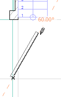
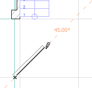
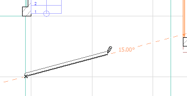
Begin your input and see the Guide Lines appear. (These are called “Instant” Guide Lines.) For example, begin drawing a wall and move the cursor around to view the available Guide Lines. You will see Guide Lines appear at fixed angle intervals, as well as Guide Lines along the X and Y coordinates.
To assist your input, constrain the cursor to the Guide Line you need by pressing Shift.
Note: This works if the Nearest Instant Guide Line box is checked in Options > Work Environment > Mouse Constraints and Methods.
Display a Guide Line Along a Particular Edge
During input, you can display a Guide Line on the edge of an existing element to help you when placing a new element. (This will be a “Lasting” Guide Line.)
To do this:
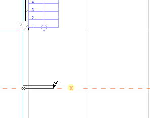
1.Move your cursor to an element edge.
2.The Guide Line handle (the orange dot) appears.
3.Click on the handle: an active Guide Line appears on that edge.
See also Guide Line Shortcut: Force Guide Line Display.
4.This Guide Line will stay in place until you complete your next input, or until you remove it manually.
For example, you want to draw a wall that aligns exactly with an existing wall.
1.Move your cursor to the edge of the existing wall and wait for the handle (the orange dot) to appear.
2.Click on the handle to activate the Guide Line.
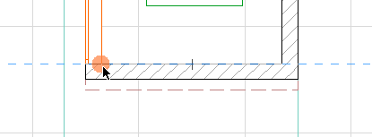
3.Now that the Guide Line is in place and active, you can draw a Wall along it.
Display a Guide Line at a Point
During input, you can display a preferred Guide Line at the status point of an existing element.
To do this:
1.Move your cursor to the point at which you want to display a Guide Line. (You are temporarily interrupting your element input.)
2.Press and hold the mouse button to see the available Guide Lines (these are “Multi-choice” Guide Lines that only appear until you choose one of them). (The cursor turns into a fist.)
See also Guide Line Shortcut: Force Guide Line Display.
3.When the needed Guide Line appears, choose it by letting go of the mouse button. (It is now a “Lasting” Guide Line.)
4.Then continue input where you left off, using the Guide Line to constrain your cursor as needed.
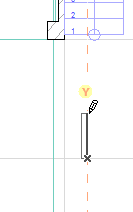
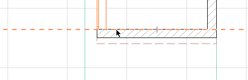
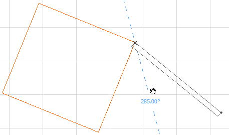
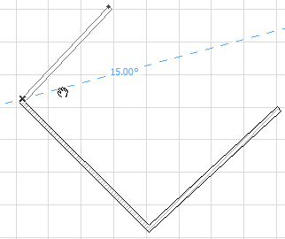
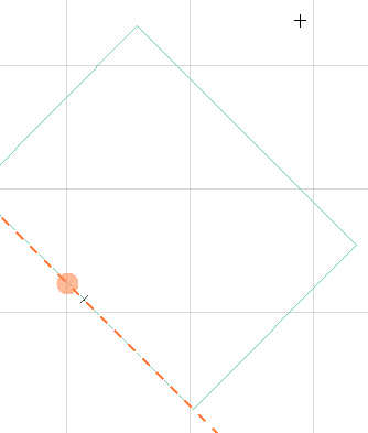
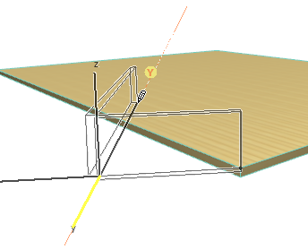
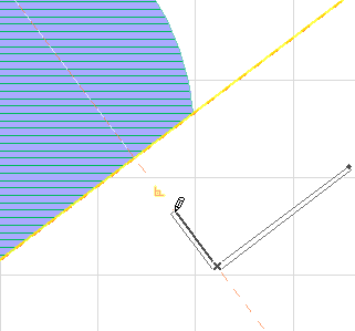
For example, suppose you are drawing this wall, and want it to extend it just far enough so that its endpoint is aligned with the vertical extension of the slab’s upper corner.
Move your cursor to the corner of the slab, then press the mouse button down to see the potential Guide Lines. (The cursor changes to a fist; your wall input is temporarily interrupted.)
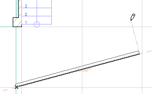
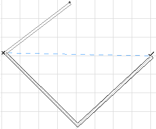
You want the Guide Line that is aligned with the slab edge: when it is shown, let go of the mouse button.
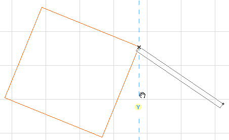
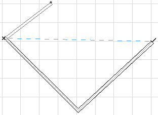
Now the Guide Line is active where you need it.
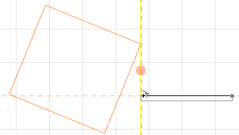
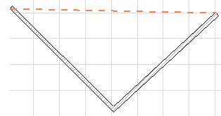
Finish your wall input up to the Guide Line.
Place Guide Line between Two Points
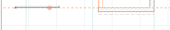
Suppose you want to place a Guide Line between the endpoints of these two Walls:
1.Draw a vector to one of the endpoints.
2.Press the mouse button down to get the multi-choice Guide Lines (the cursor changes to a fist).
3.Move the cursor to the other endpoint. The cursor changes to a checkmark.
4.Release the mouse button: a Guide Line is placed between the two points.
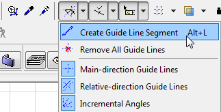
Use this command to create a Guide Line segment anywhere with two clicks.
The command is available by default in the Standard Toolbar’s Guide Lines drop-down.
Change Input Vector into a Guide Line
Independent of your default Guide Line definitions, you can place a Guide Line (or Guide Circle) at any time during input using the Place Guide Line/Guide Circle command from the context menu.
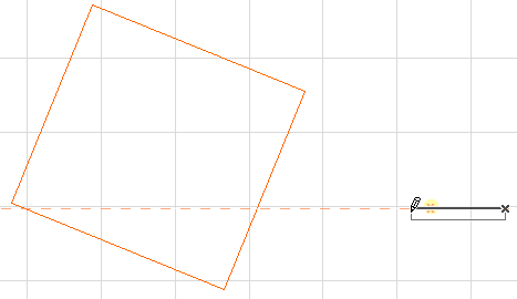
After clicking on screen to begin input, choose the Place Guide Line (Circle) command from the context menu. A lasting Guide Line (or circle) will appear.
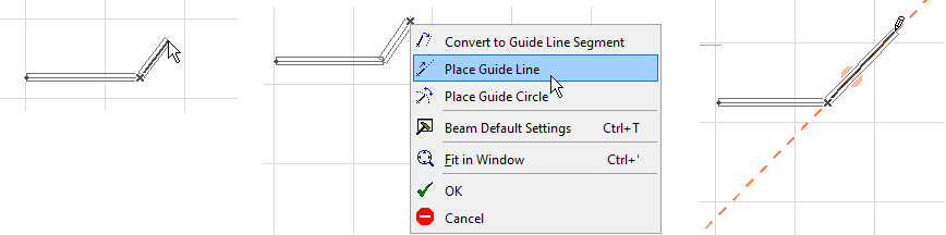
Similarly, you can use the Convert to Guide Line Segment command from the context menu. The current vector will be transformed into a Guide Line. In this case, the length of the Guide Line is limited to the length of the vector you drew and will not run across the whole screen.
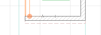
Place an Orthogonal Guide Line using Ruler
At any time, click on the Ruler at the top or left edge of the screen, and then drag your cursor to anywhere in the window: a Guide Line parallel to the Ruler is created.
See Ruler.
If you click on a Guide Line handle (the orange dot), that Guide Line becomes active.
The active Guide Line is relevant for
•constraining the input vector in a particular direction relative to this active Guide Line (e.g. parallel, perpendicular, tangential)
•defining additional “relative” Guide Lines: these are relative to this active Guide Line. One Guide Line at a time can be made “active”.
See Show Relative Guide Lines (Tangent, Parallel, Perpendicular, Angle Bisector, Circle Center).
To move an existing Guide Line to a more useful location, move the cursor to the Guide Line. Click and drag its handle (the orange dot) to move the Guide Line. (Or use the Tracker to define its new location numerically.)
See also Guide Line Shortcut: Force Guide Line Display.
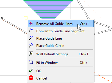
To get rid of all visible Guide Lines at once:
Right-click anywhere in the window to activate the context menu and choose Remove all Guide Lines.
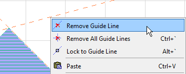
To remove a specific Guide Line, do one of the following:
•Place the cursor on it, activate the context menu and choose Remove Guide Line command.
•Place the cursor on it. Move the cursor over the handle (the orange dot) and press Esc.
Show Guide Lines at Main (X, Y, Z) Directions
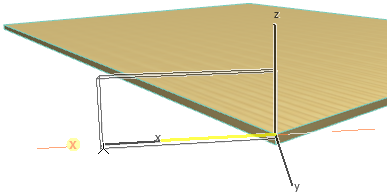
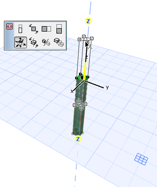
Automatic yellow highlights on the Guide Lines alert you to the main X and Y axes of the Editing Plane. In the 3D window, the Z-direction (perpendicular to the current Editing Plane) is also available during Move operations that can take place in any plane.
Note: This works if the “Main-Direction Guide lines” option is turned on in Guide Lines Options.
Show Relative Guide Lines (Tangent, Parallel, Perpendicular, Angle Bisector, Circle Center)
During input, certain Guide Lines will pop up which are relative to the active Guide Line.
Note: This works if the “Relative-direction Guide lines” option is turned on in Guide Lines Options.
The active Guide Line is shown in yellow; the relative Guide Line is marked with an icon to indicate that it is
•Tangent
•Parallel
•Perpendicular
to the yellow Guide Line.
Two other relative Guide Lines are available:
•Angle Bisector (if you begin your input at the intersection of two existing Guide Lines)
•Circle centerline (if you intersect an active Guide Circle)
(In the case of an angle bisector, you should begin your input at the intersection of two existing Guide Lines, which do not need to be active.)
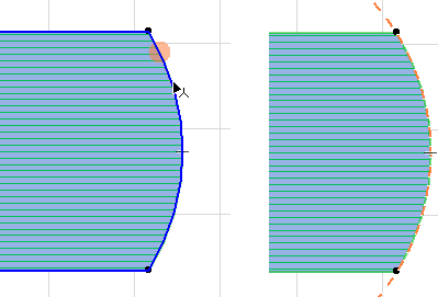
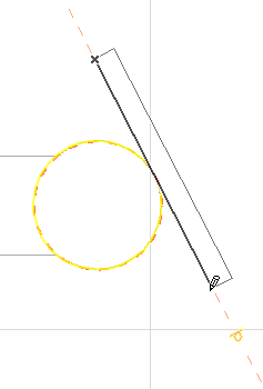
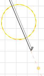
For example, a Guide Line along this curved element is currently active. As you input a Wall, a relative Guide Line, tangent to the active Guide Line, appears automatically; the yellow feedback indicates that this Guide Line is tangent to the active one. Snap to the tangent Guide Line to ensure precise Wall input.
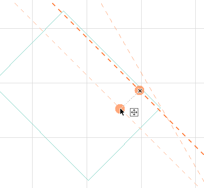
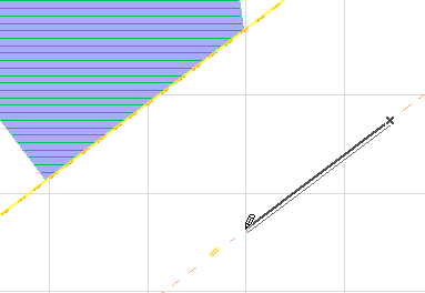
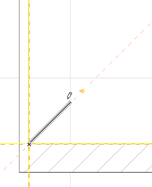
Parallel and Perpendicular Guide Lines:
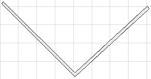
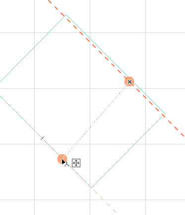
Angle Bisector Guide Line:
Guide Line Shortcut: Force Guide Line Display
“Force Guide Line Display” is a keyboard shortcut that makes using Guide Lines even smoother.
The predefined Shortcut for this command is the Q key, but may vary depending on your localized version of ArchiCAD.
Click this shortcut:
•to make multi-choice Guide Lines appear during element input, when your cursor rests on any point, without having to press the mouse button
•to create or activate a Guide Line along an edge, without having to click the Guide Line handle
•with your cursor over a Guide Line handle (the orange dot), to grab the Guide Line and move it, without having to click the Guide Line handle