Parallel and Perpendicular Constraints
Use these commands to draw new elements that are either parallel to or perpendicular to a reference line or existing element edge.
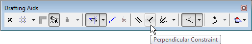
The Parallel and Perpendicular constraint commands are accessible from the Drafting Aids toolbar:
They are also accessible from the Control Box.
Note: The Control Box is not visible by default. To show it, choose its name from the Window > Palettes menu.
See Control Box for more information.
1.Make sure that the Grid Snap Function is inactive.
See Grid Snap Function.
2.Choose the Perpendicular or Parallel icon and click it to make it active.

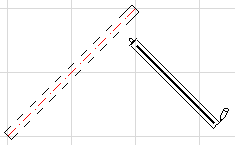
3.Select a line or an element edge as a reference by clicking it (the Mercedes feedback will indicate an edge), or draw a temporary reference line using the cursor. The cursor icon will indicate which method (parallel or perpendicular) is active.
Note: The reference edge/line will not be shown as selected; a newly drawn reference line will not remain visible on-screen.
4.Draw the new element.
The new element you draw will be perpendicular or parallel to the reference line (depending on the method selected).
Note: You can also select the Perpendicular or Parallel method after you have started drawing an element. In this case, the drawing operation is frozen until you have either drawn or selected a reference line or edge.