Note: The Control Box is not visible by default. To show it, choose its name from the Window > Palettes menu.
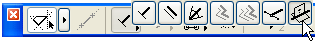
The Control Box contains a number of drawing aids in the form of icons.
Use the OK button to confirm the current operation.
Use the Cancel button to abandon the current operation.
The palette’s controls, from left to right:
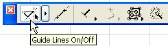
Click the toggle icon in the Control Box to turn Guide Lines display on and off.
Click the pop-up menu to access Guide Line options.
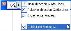
•Main-direction Guide Lines
•Relative-direction Guide Lines
•Incremental Angles
•Guide Line Settings
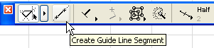
Create Guide Line Segment
For more information, see Guide Lines.
The Relative Construction Methods help geometric input by constraining the cursor’s movement to a constant angle or distance as you draft or edit elements.
Click the pop-up arrow in the Control Box to access the seven different Relative Construction Method icons.
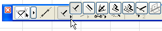
The Parallel, Perpendicular and Angle Bisector methods constrain the cursor’s movement to a constant angle.
•Perpendicular: Select an existing edge for a reference line by clicking on it, or draw a new reference line (oriented as needed) using the cursor. Draw the new element perpendicular to the reference line you defined.
•Parallel: Select an existing edge for a reference line by clicking on it, or draw a new reference line (oriented as needed) using the cursor. Draw the new element parallel to the reference line you defined.
See Parallel and Perpendicular Constraints for more information.
•Angle Bisector Constraint: Define reference vectors; use the same process as with angle dimensioning. Click to start drawing the new element. The mouse is constrained to the bisectorial angle.
See Angle Bisector Constraint for more information.
Use the Offset and the Repetitive Offset methods to create a polygonal element that is offset from a reference line.
See Offset and Multiple Offset Constraints (Relative Construction Methods).
•The Special Snap Vector method lets you draw a temporary vector that displays your defined special snap points, to aid in accurate placement of elements.
See Special Snap Points on Temporary Vector.
•The Align to Surface method works in 3D only.
Select an existing surface by clicking on it. Place the element on the section line of the input plane, and the surface you defined.
For more information, see Aligning Elements to a Surface in 3D.
This set of icons controls the way the current position of the cursor is projected on the rubber band line constrained to a predefined direction. Cursor Snap becomes active when you start drawing a vector.
For more information, see Projection of Cursor with Mouse Constraints.
These two icons act as a toggle and have the same effect as the Suspend Groups toggle command. If Suspend Groups is active, grouped elements can be selected and edited one by one.
For more information, see Group Elements.
With the Magic Wand feature, ArchiCAD allows you to trace the outline of shapes for creating elements. Effect of Magic Wand depends on Tool and construction method selections.
For more information, see Magic Wand.
Special Snap Points (Control Box)
With this method, you can place a node at the division point of a temporary vector defined on the fly. Division point(s) will be calculated based on the current Special Snap Point settings.
Activate the Special Snap Point toggle.
Hover your cursor (it should be a Mercedes shape) over the edge on which you want to make the points appear.
Snap Points Menu:
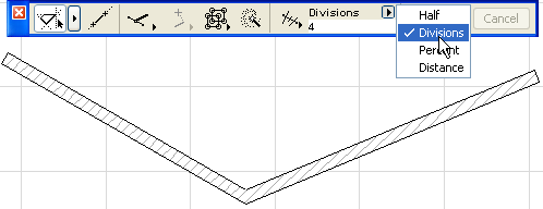
•Half: Divides an edge into two equal parts.
•Division: Divides an edge into the set number of segments. (Range: 3-20) (Enter the number of divisions into the field below.)
•Percentage: Divides an edge into two parts according to the set percentage. (Enter the percentage into the field below.)
•Distance: Divides an edge into segments that are the set distance apart. (Enter the distance into the field below.)
Distances and percentages are always calculated from the endpoint that is closest to the cursor.
When the Special Snap Points Relative Construction Method is ON, and the cursor changes to the Mercedes form on edges of elements, special snap points are automatically generated. Special points only appear temporarily and will disappear after 4-5 seconds. Special Snap Points options include: Special Snap Points disabled, Special Points work on the whole element, Special Points work on the part of the element between two intersection points.
Another way to set custom values for Division, Percentage and Distance methods is to open the Set Special Snap Values dialog box (View > Special Snap Options > Set Special Snap Values menu command).
For more information, see Special Snap Points.