
Using the Angle Bisector relative construction method, you can draw elements bisecting the angle formed by other elements or temporary reference vectors.
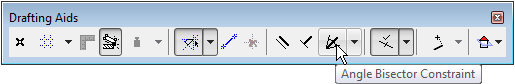
This command is accessible from the Drafting Aids toolbar:
It is also accessible from the Control Box.
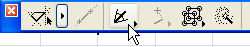
Note: The Control Box is not visible by default. To show it, choose its name from the Window > Palettes menu.
See Control Box for more information.
You can either start drawing the new element before activating the Angle Bisector method and defining the reference vectors, or the other way round. Before using Angle Bisector constraint, make sure that Grid Snap is disabled.
Click the Angle Bisector icon, then define the reference vectors by either clicking on two existing element edges or lines, or drawing two temporary lines. While you are clicking or drawing the reference lines, the cursor icon will show that you have activated the angle bisector constraint.
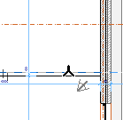
(The reference edges/lines will not be shown as selected; the temporary lines will not remain visible on-screen.)
The mouse is constrained to the bisecting angle between the two reference lines. Before you actually draw the element, the cursor is already constrained, and you can see a small black dot move along the line that would be drawn at that angle.
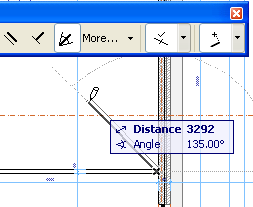
As for any other constraint, you can use remote cursor snap to define the other endpoint of the drawn line.