 .
.In Zone Settings, customize the parameters of your zone - such as its name, its category, its height, and the content of its zone stamp. Then you are ready to define the zone shape, either on the Floor Plan or in the 3D Window.
The bottom of every Zone (like other elements) is linked to its Home Story; you can also top-link the Zone to any story above it in the project. As needed, define offsets from its top link or Home Story; this will affect the Zone height. Alternatively, just enter a fixed Zone height, without a top link.
See Zone Tool Settings and Home Story and Define Top Link for Wall, Column or Zone.
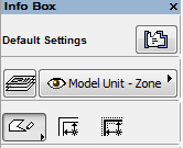
The Zone definition methods are represented by the three icons in the Info Box.
You can either:
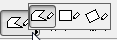
•manually draw the contour of a zone (using the Polyline, Rectangular or Rotated Rectangular Methods); or
•let ArchiCAD automatically recognize a zone surrounded by bordering elements (using one of the two Automatic Recognition methods):
.
See Automatic Recognition Methods.
Note: Columns cannot serve as the enclosing boundary of a zone.
Manual Methods
Use one of the manual methods when your Zone’s boundary is not clearly surrounded by elements (e.g. when doing space planning).
1.Activate the Zone tool.
2.Do one of the following:
•Draw a polyline (as you would for any other polygon) by clicking at every corner of the zone; or
•Use the rectangular/rotated rectangular methods to draw a rectangle.
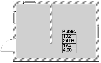
3.Click with the appearing Hammer cursor to define the location of the Zone Stamp. (The Zone Stamp does not necessarily have to be placed inside the Zone polygon.)
You can edit a polygonal zone graphically by selecting it and using the pet palette commands.
See Edit Zone Polygon.


Both automatic recognition methods, Inner Edge and Reference Line, are based on the fact that most Zones are surrounded by Walls and the only openings in them are Doors and Windows.
•If you choose the Inner Edge method, ArchiCAD will always define the zone area by the inner edges of walls.
•If you choose the Reference Line method, ArchiCAD considers the reference lines of the walls as the boundaries of the zone. Note that even if you constructed Walls with the reference line placed on the external edge, the Zone fill does not overlap the wall symbol until you choose Bring to Front from the Edit > Display Order.
Note: In case of a slanted or complex wall, the Reference Line method will not consider the wall’s reference line, but rather its inner edge.
Exclude a Wall or Column as a Zone Boundary
By default, the Relation to Zones setting in the Listing and Labeling panel of Wall or Column Settings is set to “Zone Boundary.”
This means that all walls/column enclosing a closed space are considered zone boundaries by default.
To exclude any wall/column as a zone boundary, just change the Relation to Zones setting to No Effect on Zones.
See also Relation to Zones.
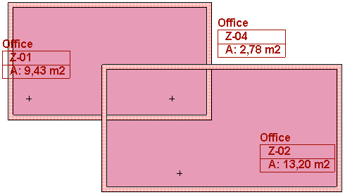
If you place the Zone Stamp with one of the automatic recognition methods, you will see a cross appear inside the Zone at the location that you first clicked to define the Zone’s area. This cross indicates the reference point of the Zone.
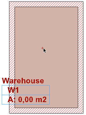
This point is used as the starting point of boundary recognition for subsequent updating actions.
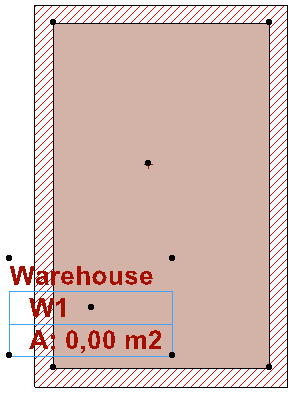
Use the familiar pet palette commands to edit the zone polygon.
See Reshaping Polygons and Chained Elements, and Offset All Edges.
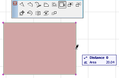
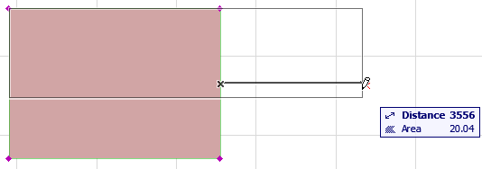
Use this pet palette command to offset the clicked edge in such a way that the original Zone area does not change. This is useful if you are doing space planning based on defined areas.
In this example, you offset the right side of the zone - and the shape is automatically constrained so that the area stays constant (as seen in the tracker):
Create a Manual Zone Boundary
If the Zone has openings that are not Doors or Windows, ArchiCAD will continue searching for boundaries outside the spatial unit that you wished to identify as a Zone. In this case, the result may not be what you expect (see figure, below right).
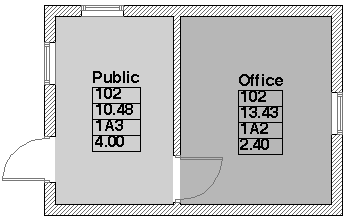
In this case, close the Zone by:
•using the Polygon method
•place an Empty Opening Door object into the Wall which is the same height as the Wall - the Wall is not shown in 2D, but it does serve as a Zone Boundary
•drawing a line to serve as a Zone Boundary
You can draw a Line, Arc or Spline to serve as a zone boundary if you check the Zone Boundary checkbox in its Line Settings dialog boxes.
If your desired zone boundaries also encompass freestanding shapes or walls, you may get a warning message when clicking to place the zone stamp.
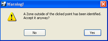
If this happens, you must click closer to the bounding elements. Then the zone will be created correctly.
Related Topics: