Automatic Interior Dimensioning
The Automatic Interior Dimensioning Dialog Box contains options for dimensioning Columns and composite or profile (complex) elements.
Note: Profiled Columns will be ignored.
Open this dialog box from Document > Document Extras > Interior Dimensioning.
Choose preferred dimensioning options.
Use the first two options to set the way you wish to dimension columns.
Column Center: Dimension the axis of the column
Column Endpoints: Dimension the endpoints of the column.
Note: A circular column will always be dimensioned at its center regardless of the state of this checkbox.
Composite and Profile Elements: Use a combination of these two checkboxes to determine how the skins of composite and profile elements should be dimensioned.
•Dimension Each Skin: Each skin of the composite/profile element is dimensioned separately. (If this is unchecked, a single dimension is applied to the total width of all the skins.)
•Dimension Core Only: Only the skins (components) that are part of the core of the composite/profile element are dimensioned. You can dimension each skin/component of the core separately (if you also check the “Dimension each skin” box above), or dimension the core as a whole (if you leave the above checkbox unchecked.)
Note: This checkbox has the same effect as the “Dimension only the Core of Walls and Slabs” checkbox in the Dimension Details panel of Dimension Tool Settings. Therefore, elements with no core will be ignored.
See Dimension Core Only of Walls and Slabs.
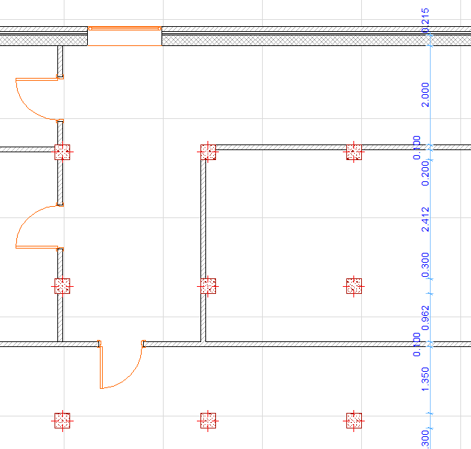
Next, draw a line across the selected elements. Walls, Columns, Beams, and Slab, Roof and Mesh edges perpendicular to or crossing the drawn line will be dimensioned. The line can consist of several segments. Double-click to finish drawing the line. An additional click is needed to determine the place of the dimension line. After placing the dimensions, the crossing line disappears.