
Open this dialog box from the Model Review Palette’s pop-up at the top right; or from Design > Energy Evaluation > Environment Settings.

The Environment Settings dialog contains:
•Settings: Location and Climate, Grade Level, Soil Type, Surroundings
•Links to other dialogs: Project Location, Climate Data, Surface Heat Transfer, Wind Protection, Horizontal Shading
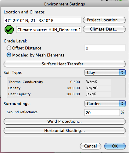
Energy Evaluation considers the geographic location of your building when obtaining Climate Data from the StruSoft Climate Server. Use the Project Location button on the Environment Settings panel to access the Project Location dialog of ArchiCAD.
See Project Location and Project North.

This control is in the Environment Settings dialog box.

The connection of the ground with the building can be modeled in two ways in ArchiCAD for Energy Evaluation:
•Offset distance: the distance by which the pavement is offset from either Project Zero or a predefined Reference level.
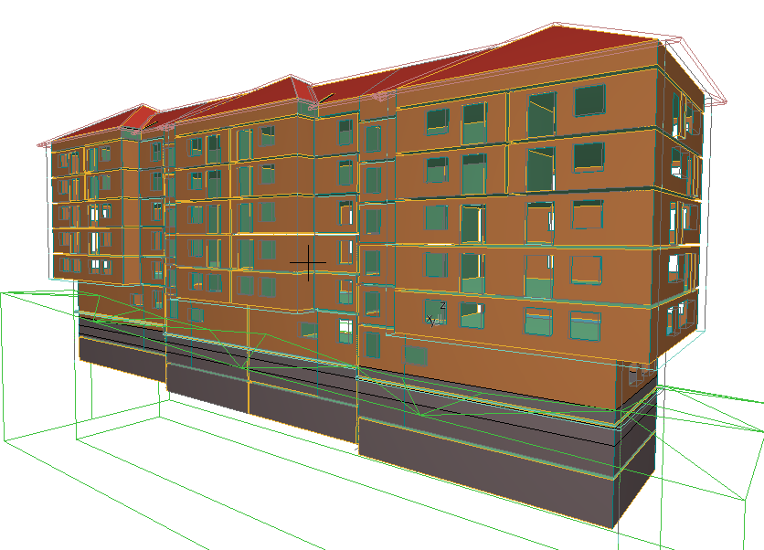
•Modeled by Mesh elements: use the Mesh tool to model the site around the building, if it is not completely level, for better energy modeling accuracy of structures in contact with the ground.

This dialog is used to define Internal and External combined heat transfer coefficients for all opaque structures in the project. While the surface coefficients entered on the U-Value Calculator influence only the stationary thermal performance calculations on the level of individual structures, the global settings on the Surface Heat Transfer panel are used for the dynamic energy balance simulation.
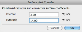
Users are advised to change the default global surface coefficient values only if local standards specifically require the use of other values.
From the pop-up, choose the option that most closely describes the soil type of the building location. This setting serves as the basis for calculating heat flow through structures in contact with the ground.


The applicable Thermal Conductivity, Density and Heat Capacity values are then displayed below your chosen soil type.
Choose the Surroundings option that best describes the environment of your building: Waterfront, Garden, Paved or Custom.


This setting is used when calculating the effect of indirect solar irradiation.
From the Environment Settings dialog box, click Wind Protection to open the dialog box of the same name.
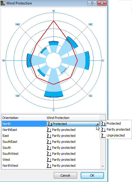
The polar diagram represents the 8 main directions. The length of each segment represents how often (as a percentage, over the course of a year) the wind blows from the given direction, and how fast.
Here, for each orientation of the building, choose the appropriate Wind Protection level: Protected, Partly Protected or Unprotected. For each orientation, a point is placed on the graph representing wind protection (the further out the point, the higher the protection factor), and the points are connected by a red line.
The model-based Solar Analysis function of Energy Evaluation in ArchiCAD only works on the transparent elements of the building shell. However, it does not automatically determine the extent to which shadows are cast by external objects on the opaque elements of the building envelope.
Use the Horizontal Shading button to activate a separate dialog with a list of those sides of the building that receive the sunlight (the list of Orientations can vary depending on project location).
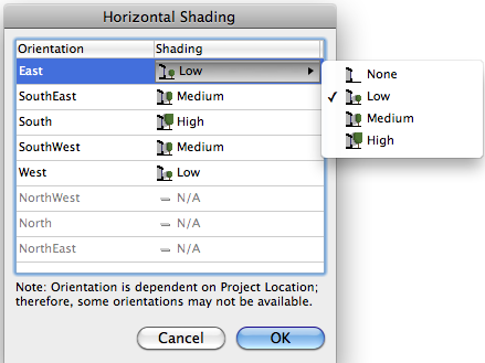
For each orientation, choose the options that best describe the amount of shading resulting from external objects (select an option - None, Low, Medium or High).