Project Location and Project North
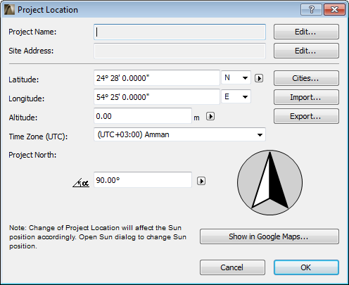
Use the Project Location dialog box to identify the geographical location of your project.
Location Settings are significant for:
•Running the Energy Evaluation function
•Calculating Sun position for 3D views, camera views, photorenderings, and Sun Studies
•ArchiCAD Library parts which refer to the Project North value you set here.
See Project North.
•The Google Earth Connection add-on, which considers the Altitude

The Project Location dialog box is available:
•from Options > Project Preferences > Project Location
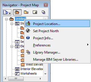
•from the context menu of the Project Name in the Navigator
•from the Sun dialog box
See Sun.
Project Name and Address
The data for Project Name and Site Address are taken from the Project Info dialog box.
See Project Info.
Click Edit to modify these data by opening the Project Info dialog box.
Enter Location Data
Enter the Latitude and Longitude of the Project Location.
For maximum accuracy (e.g. for Energy Evaluation purposes), you should identify and fill in precise latitude/longitude data for the location of your project.
Click the pop-ups to switch between Latitude North and South, and Longitude East and West.
Choose your preferred unit of measure from the fly-out menu.

Altitude: Enter the altitude of the project location in the desired units. (Altitude data is used when you export the project to SketchUp and Google Earth formats Altitude is also used as the Sea Level Reference Level for your project, at Options > Project Preferences > Reference Levels.)
See SketchUp (.skp) and Google Earth (.kmz).
Time Zone: Choose a time zone at the Project Location, expressed as a positive or negative offset from UTC (Coordinated Universal Time), together with the name of the corresponding time zone.
Use Predefined City as Location Data
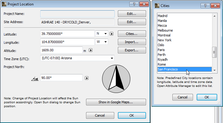
As a quick way to enter Location data, you can choose a predefined city: click Cities at the right side of the Project Location dialog box.
Note: To edit the list of predefined cities and associated data, go to Options > Element Attributes > Attribute Manager.
See Attribute Manager.
Choosing a predefined city will fill out the Latitude, Longitude and Time Zone fields.
Note: However, for maximum accuracy, you should prefer precise latitude/longitude data for the location of your project, rather than a predefined city.
Use Google Maps to View and Query Location Data
Provided you have an Internet connection: click on Show in Google Maps to view the project location as defined by your latitude/longitude data.
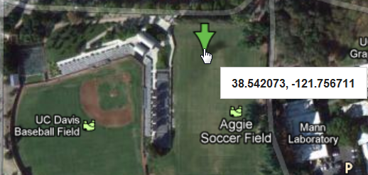
To query precise data using Google Maps, zoom in to the desired location. Right-click to bring up the context menu, then choose “What’s Here?” to view (and copy, as needed) latitude/longitude data.
Enter an Azimuth (compass) angle value here to orient the Project North direction in the Floor Plan window, or drag the compass pointer to orient the Project North Azimuth graphically.
From the pop-up, choose the display unit for Project North.

Note that the accuracy of these units depends on the accuracy set for Angle Unit in Options > Working Units.
Another way to set Project North is graphically, right in the project:
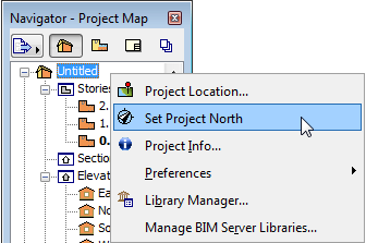
•Click Options > Project Preferences > Set Project North, or
•Use the same command from the context menu of the Project Name in the Navigator (provided that the Floor Plan or 3D Window is open).
In either Floor Plan or the 3D window, move the pointer to match the project’s North orientation.
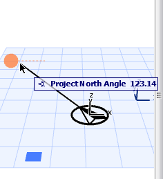
The Project North value affects the following:
•The calculations of the Energy Evaluation function.
•Some Interior Elevation Markers include text which display the Project North value.
•The North Symbol object (in the ArchiCAD Library), when placed in the project, reflects the Project North value. (You must check the “Follow Project North” box in the object’s Settings.)
•When using surveyor’s units (Options > Project Preferences > Working Units), the North of the Coordinates Palette and the Tracker will be the same as the one set here.
•The Sun azimuth will be calculated with respect to Project North (where East is at 0.00 degrees).
See details on sun position at Sun.
Manage Location Data (XML, SketchUp, Google Earth)
Use the Import and Export buttons to manage the information displayed in this dialog box.
There are three possible formats: XML, Google Earth (.kmz) and SketchUp (.skp).
All three formats can be used to transfer information between ArchiCAD projects. The Google Earth and SketchUp formats also allow users to align their ArchiCAD models with SketchUp and Google Earth models.
•The XML format stores and reads longitude & latitude, angle display format, time zone, altitude & altitude unit, north direction and display format.
•The Google Earth (.kmz) format stores longitude, latitude & altitude as a single place mark. The import function will also read longitude and latitude data from .kmz files containing a single place mark. The altitude will also be imported if it is expressed in absolute mode (not relative or clamped).
•The SketchUp (.skp) format exports and imports longitude, latitude, altitude, North direction and time zone. The Site Address:-city and Site Address:-country data are exported but NOT imported).
For further information on SketchUp:
•import: see SketchUp (.skp)
•merge: see Merge SketchUp (.skp) File
•export: see SketchUp (.skp)
For further information on Google Earth:
•import: see Google Earth (.kmz)
•merge: see Merge Google Earth (.kmz) File
•export: see Google Earth (.kmz)