
Use this dialog box to define Building Systems settings that will maintain the internal comfort conditions (as specified by the Operation Profiles dialog) for the thermal blocks of your building model.
You can either select from the defaults or define custom Building Systems, which you will assign to each Thermal Block.
Open the Building Systems dialog box from the Model Review Palette’s pop-up at the top right, from Design > Energy Evaluation > Building Systems, or from the Thermal Blocks page of the Energy Model Review palette.

The Building Systems dialog box lists each Building System on the left, and the options for each on the right. The content of the building system options on the right changes depending on which system configuration is selected. Use the Building Systems dialog to edit the properties of existing building systems, to create new ones and to assign them to thermal blocks.
View or edit the list of thermal blocks that use the selected system.

Note: It is also possible to assign systems to thermal blocks via the Thermal Blocks page of the Energy Model Review palette.
Press the Energy Source button from either the Boiler or Furnace tab page (Heating System) or the District Cooling Settings tab page (Cooling System).

In the appearing Energy Source dialog box, click on a listed Source item and use the dropdown to specify energy sources (Natural gas, Propane, Oil, Wood, Coal, Electricity or Pellet) for the Boiler/Furnace or Cooling System.
If you use more than one energy source for a function, click the + (plus) button, then choose an additional energy source.
Define the proportion of each source used so that the Total adds up to 100%.
To remove a row, click the – (minus) button.
In the table below, the energy sources used by Energy Evaluation are listed according to their type and with their colors as displayed on the Energy Balance Evaluation report.

Choose either District Heating or On Site Equipment to describe the building’s heating system.
District heating means that the evaluated building’s heating and/or hot water needs are supplied by an external plant in the form of hot water or steam through a pipeline.
Use the Energy Source button to define the source or multiple sources of energy consumed by the heating system, as applicable.
See Energy Source dialog box.

Choose one or more equipment types corresponding to the heat source to be used:
•Boiler or Furnace
•Solar Thermal Collector
•Water Heat Pump
Each option’s settings are located on the corresponding dialog box panel below.
Fine-tune heater performance data such as Capacity and System Heat Loss or use the smart defaults provided by the program.
Specify whether or not to Include Service Hot-water Generation

Use the Energy Source button to define the source or multiple sources of energy consumed by the heating system, as applicable.
See Energy Source dialog box.
Solar Thermal Collector Settings
Solar thermal collector panels are designed to collect heat by absorbing sunlight and converting the energy in solar radiation into a more usable form.
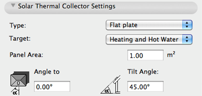
•Type: Choose either Flat Plate or Evacuated tube.
•Target: Set the target for the recovered solar energy: Heating, Hot Water, or both.
Note: If solar collectors are used for multiple targets, then Hot water generation always has the highest priority. This means that if the solar collector is unable to generate enough energy to feed all targets, then it is going to feed the water heater first and use the remaining available energy for the Space heating.
Specify the collector geometry data required for the calculations:
•Panel area
•Orientation angle to the South (or to the North, for southern hemisphere locations)
•Tilt Angle
Specify system target and priority (drag-and drop the list items in the desired order) as well as source.

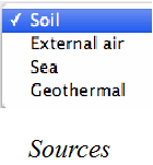
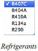
System parameters can also be fine-tuned, or use the smart defaults provided by the program.
Enter Cold and Hot water temperature target values. The calculation engine uses this data to calculate the energy consumption related to hot water generation.

To change the temperature scale (Celsius or Fahrenheit), click the arrow button next to the input field.
Note: For other units (apart from temperature scale), Energy Evaluation uses the units defined in ArchiCAD, at Options > Project Preferences > Calculation Units and Rules.
See Calculation Units and Rules Preferences.
Use the right side of the dialog to describe the building’s cooling system, or use the smart defaults provided by the program.

•Cooling Machine means that some type of cooling system is to be installed in the building. Click Characteristics to see and edit the performance graph of the cooling system.
•District cooling: In certain countries, cooled air may be obtained from an external source. If the building will be connected to such an external cooling system, select District cooling and use the Energy Source button.
See Energy Source to define the source or multiple sources of energy used by the district cooling plant.
Specify the type of ventilation used in the building: “Not Yet Specified Or Natural” or Mechanical Ventilation. Both of these ventilation types can be defined with Steady Air Change Rate as well as Time Scheduled Air Change Rate.

Not Yet Specified Or Natural Ventilation
Natural ventilation involves no MEP systems: natural air currents drive fresh air into the building and used air out of it. From an ecological point of view, natural ventilation is preferable to mechanical solutions, but due to its limited controllability its use is largely limited to residential buildings.
Mechanical
For building functions other than residential, the standards usually prescribe strict target air exchange values, which necessitate a mechanical ventilation system of some sort:
•Supply-only systems rely on fans to drive fresh air into the thermal block.
•Exhaust-only systems rely on fans to extract used air from the thermal block.
•Supply and exhaust systems mechanically control both the air intake and outlet procedure.
•Heat Recovery: Mechanical ventilation systems may or may not have air-to-air heat recovery units. Use the dedicated checkbox to specify this setting.
Note: The Air to air recovery controls are available only if you have chosen a ventilation system that involves mechanical exhaust. If your ventilation type is set to Natural, these controls are inactive.
An air to air energy recovery system can regain a percentage of the heat content of mechanically expelled ventilation air.
•Steady Air Change Rate: Enter a value for the hourly air change rate. This target value depends on national standards, and will vary depending on the building’s function and the local climate.
•Time Scheduled Air Change Rate: Supply and exhaust data may vary by day of the week and over the course of the year. The ventilation Operation Schedule can consist of any number of daily schedules, which correspond to specific date ranges and days of the week.

For each daily schedule, you can define the following characteristics:
•Recurrence: days of the week when the particular schedule is in effect
•Date Range: periods of the simulation year during which the schedule occurs
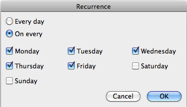
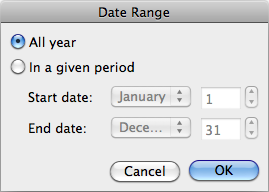
Recurrence and Date Range define the In use hours (the total number of hours during which the selected Daily Schedule is in effect).
If the Out of Operation hours counter on the bottom right corner of the Yearly Operation Scheduler shows any number except 0, it means that further modifications in Recurrence and Date Range are necessary because there are some hours of the reference year without operation schedule assigned to them.
If the Overlapped hours counter on the bottom right corner of the Yearly Operation Scheduler shows any number except 0, it means that further modifications in Recurrence and Date Range are necessary because there are some hours of the reference year with more than one operation schedules assigned to them.