
The GDL Object Editor contains all controls needed to edit a GDL object.
For a detailed description of scripting commands and object-level editing, see the GDL Reference Guide (available from the ArchiCAD Help menu).
To open the GDL Object Editor, do one of the following:
•For a placed object: select the object, then use File > Libraries and Objects > Open Object (or choose this shortcut command from the Edit GDL Library Parts toolbar)

•For any object file (and if no placed object is selected): use File > Libraries and Objects > Open Object, then browse for the desired object.
•Another way to browse for an object is by subtype: use the Open Object by Subtype command from the Edit GDL Library Parts toolbar.

The window that opens is the GDL Object Editor.

Use the buttons on the left side to open different tables/lists for editing (e.g. Details, Parameters, Components) within the GDL Object Editor.
The Script editing windows (e.g. Properties Script, Parameter Script) can be opened in two ways. If you click the button itself, editing will take place inside the Master Window. Clicking the window icon next to the script’s name will open a separate window for entering or modifying the script.
“Read-Only” Objects from a Library Container File
To edit an object placed from a library container file, you must first extract the container. Otherwise, the Object Editor Window is “Read-Only”.
For more information, see Library Container File.
Topics in this section:
The controls of the GDL Object Editor are described in the following sections.
Compatibility Options (Developer Use Only)
Compatibility Options (Door-Window) (Developer Use Only)
Check Object’s 2D and 3D Views
The Preview Picture window can be viewed in one of six formats.
•Click one of the buttons beside the window to choose a display option for the preview picture: 2D Symbol (drawing), 2D Full View, Elevation, Hidden Line, Shading, and Rendered Preview.
•With the Elevation, Hidden Line, or Shaded display options, you can click in the preview window to rotate the image in 45 degree increments.
Object’s subtype: Displays the subtype of the open object.
•You can change an object’s subtype by clicking the Select Subtype button, which will open the Subtype Hierarchy dialog box. Changing the Object’s subtype modifies its behavior and adds the parameters and functionality needed for the new subtype. For example, you can change a plain object into a light source by changing its subtype to Light.
For more information, see Subtype Hierarchy Dialog Box (GDL Master Window).
Use as subtype: If you check this box, the object will be saved as a template to be included in the list of available Subtypes. The new template will appear in the Subtype Hierarchy dialog box, and any new objects that you associate to this subtype will take on all of the parameters of the subtype.
The Placeable checkbox is enabled by default. If you uncheck it, the Object will behave as a macro. If this box is unchecked, this means that
•it will not appear in any of the tool settings dialog boxes;
•you will not be able to place it directly in the project;
•it cannot be included in an archived project file;
•but you can refer to its scripts from other Objects.
Object Information Fields
The next few controls are relevant if you wish to share the library part to the BIM Components Portal, or if you plan to make your own object commercially available. Also, any text you enter will be considered when you use the Search function for locating library parts through a library part Settings dialog box.
Edit the following information as needed:
•Enter an Author. (If you leave this blank, the name you used to register on the BIM Components Portal will be used as the author, after the object is shared.)
•Assign a Copyright. Three options are available here:
-Public Domain Dedication. Click the Info button to navigate to a webpage containing details: http://creativecommons.org/publicdomain/zero/1.0/
-Attribution NoDerivs. Click the Info button to navigate to a webpage containing details: http://creativecommons.org/licenses/by-nd/3.0/
-Commercial. Use this kind of copyright if you are selling the object over the internet. An object with Commercial copyright cannot be shared to the BIM Components Portal. Click the Info button to navigate to a webpage containing details.
•Password (available if the copyright is “Attribution-NoDerivs0” or “Commercial.”). Click Set Password to define an optional password. Such objects can be freely viewed and downloaded, but the user cannot open the object to edit or copy its script without a password.
•Description. Enter an optional description of the object. This text will appear when you click the Info button in the Settings dialog box, as well as in the BIM Components Portal, if the object has been shared there. Also, Description text will be considered when you use the Search function for locating library parts through a library part Settings dialog box.
Compatibility Options (Developer Use Only)
The Compatibility Options dialog box, accessible from the GDL Object Editor’s Details page, concerns item (instance) sizes.
Note: Doors and Windows have different controls in the Details dialog box: see next section.
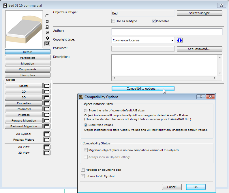
Object Instance Sizes: Use these radio buttons to set how you want your placed objects (object instances) to store their parameter values.
•Store the ratio of current/default A/B sizes: Placed objects will proportionally follow any changes in default A and/or B parameters.
•Store fixed values: Placed objects will not change when their default A/B parameters are later changed.
•Migration object (there is no new compatible version of this object)
•Always show in Object Settings
These controls are used only by developers working with ArchiCAD Library objects. The checkbox denotes objects that will not automatically receive new counterparts in newer library versions.
Hotspot on bounding box: Check this box (if applicable) to place five hotspots at the edges of the 2D symbol of the Library Part. These are independent of hotspots defined in the part’s GDL script. These five hotspots will be located at the four corners and at the center of the symbol’s bounding box. The default hotspot used for placement of the object on your Project will be the lower left one of the five. (This is indicated by a heavy square highlighting the hotspots on the 2D symbol in the Tool Settings dialog for the Library Part, where you can change the active hotspot.)
If you do not want the lower left corner of the bounding box to be the default hotspot, leave the checkbox unmarked and write the required hotspot(s) into the GDL script. In this case, the default will be the first hotspot encountered in the script.
If neither bounding box nor GDL hotspots are specified, ArchiCAD will place hotspots at the corner of the Library Part bounding box and use this as the default.
Fit Size to 2D Drawing: Check this box to transfer the current 2D Symbol’s A and B axis dimensions into the default A and B dimension fields of the Master Window.
Compatibility Options (Door-Window) (Developer Use Only)
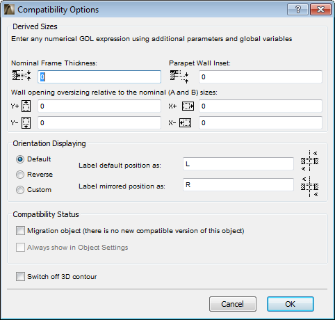
Derived Sizes: Use the edit fields in this section of the dialog box to define the geometric relationship between the wall opening and the Door or Window. Use numerical GDL expressions.
•Nominal Frame Thickness: Specify the Nominal Frame Thickness here.
•Parapet Wall Inset: Specify the Parapet Wall Inset here.
•Opening Oversizing: Specify opening oversizing relative to the nominal (A and B) sizes here for Y +, Y- (at the top and bottom) and X +, X- (at the right and left).
•Orientation Displaying: Use these controls to define the way the opening’s orientation is displayed (e.g., with R for right and L for left).
•Default: Click this button to display Door/Window opening orientation as a standard default setting.
•Reverse: Click this button to display Door/Window opening orientation in reverse as a standard default setting.
•Custom: Click this button to customize the display of Door/Window opening orientation.
Compatibility Status (Developer Use Only)
•Migration object (there is no new compatible version of this object)
•Always show in Object Settings
These controls are used only by developers working with ArchiCAD Library objects. The checkbox denotes objects that will not automatically receive new counterparts in newer library versions.
Switch off 3D Contours: Check this to hide the 3D contour of the selected Door/Window object (when shown in Wireframe or Hidden Line modes).
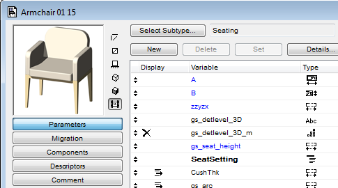
Click the Parameters button to display the Parameters of the current Library Part in the editing area.
Search Parameters: Enter a text string in the search field to locate any part of that string in the Variable, Name, or Value columns. The cursor jumps to the first found instance. Use the Find next/Find previous buttons to jump to additional found instances.

By assigning values to the set of variables in the Parameters list, you will define the attributes of a particular GDL Object. The values assigned here will be the default values found in the Settings dialog box when you choose a tool that uses GDL Objects. These locally defined Parameters can also be called by the different Scripts of the Object.
The parameters that appear in blue are the obligatory parameters (such as A and B dimensions) that belong to the edited Object’s subtype.
Optional parameters are available for use in the Object’s GDL description. The values specified for them will become the default additional values displayed when you open the appropriate Settings dialog box from the Toolbox.
The optional parameters are typically used to define such things as the number of window panes or door panels, the usual surfaces of a part, etc.
New parameters can be created by pressing the New button at the top of the Master Window. Remove existing parameters by selecting them in the list then pressing Delete next to the New button.
Each parameter in the list can be edited in its own row. Each line consists of an icon (required) indicating its type, the parameter letter or a string variable, a descriptive text (optional, but recommended) and a default numeric value.
Highlight the row you wish to edit. For obligatory parameters, you cannot edit the variable name or type icon. For optional parameters you can edit all the parameters.
The Type icons control how the values are interpreted by ArchiCAD. Clicking a Type icon displays a dialog box where you can redefine the parameter’s type by choosing another icon.
The parameter types (identical for obligatory and optional parameters) are the following:
•Length:
specifies physical dimensions of the GDL Object (and makes conversions to whatever units you are using.) Must be a positive number.
•Angle:
specifies angular values in decimal degrees for such GDL operations as rotation transformations and defining arcs.
•Real Number:
specifies decimal non-dimensional values (any real number) for uses like including a magnification factor in a GDL calculation.
•Integer:
specifies whole numbers, dimensionless values for uses like defining the number of identical components in a GDL description or the number of times to loop through a part of the GDL Script.
•Boolean:
the value of a Boolean parameter can only be 1 or 0 for uses like activating or deactivating an action or an item in a GDL Object. These values can either be typed directly into the value box, or set by clicking the checkbox at the right end of the parameter line.
•Text:
specifies character strings up to 255 characters for uses like defining changes in the GDL Object or typing plain words instead of numbers in the parameter’s value box.
•Surface:
specifies a surface as a GDL parameter.
•Line Type:
specifies a line type as a GDL parameter.
•Fill Pattern:
specifies a fill pattern as a GDL parameter.
•Pen Color:
specifies a pencolor as a GDL parameter.
Note: If any of the Surface, Line Type, Fill Pattern or Pen Color parameter types is selected, a button appears at the right end of the parameter line where you can bring up a pop-up list of corresponding settings. Any of the attributes currently available to ArchiCAD can be chosen.
Note: Depending on how you write your GDL descriptions, the parameters you use can affect both the 2D and 3D aspects of the Library Part.
Parameter Types include two further options: Separator and Title.
These are virtual parameters as they are only used to make the Parameter List more organized and easier to view.
To further organize and format the parameter list, use any of the list formatting icons, visible only when a list item is highlighted.
•Pressing the first icon, Hide Parameter, will remove the highlighted parameter from the Parameters panel in the Object Settings dialog box.
•The second icon, Subordinate, will create a hierarchy among parameters. When a parameter is ordered under another one, the subordinate parameters appear in a sublist within the parameter list of the Object Settings dialog box. The sublist can be opened and closed by pressing the small triangle next to the superior parameter. The superior parameter can be of any type; however, a Title type parameter cannot be subordinated.
•Pressing the third icon, Bold, will make the parameter name appear in bold type.
•The fourth, Unique icon (if activated) means that the current parameter will NOT be transferred if you transfer the rest of this object’s parameters to another object.
See Parameter Transfer Between Objects.
You can restrict the possible values of a parameter by defining an array.
When you highlight an array item in the parameter list, a button appears next to the Type icon.
Click it to toggle between a single or value list and an array. If it is toggled to array, clicking it will open the Array Values dialog box.
Note: Once array values have been defined for a parameter, the Array Values dialog box can only be opened by pressing the Set button at the top of the Master Window.
Click on the Insert and Delete buttons to add rows or columns. Edit the fields of the array by clicking on the fields, then entering the value in the number field at the right side. Where variable types allow, you can choose values from a pop-up menu.
To insert or delete a row or column, select the button showing the row/column number, then press Insert or Delete.
Click the Migration button to open a table in which to define the older-version objects that should be migrated to the currently opened (newer-version) object.
•Fill in the main GUID of any old object that can be migrated to this new, currently opened object.
•Fill in a version number for the old object (typically the version of a previous ArchiCAD): when the project is saved back to the previous version (and if “Convert library objects backward” is set in Options from the Save As dialog box), this new object will be migrated to an old object in the migration table which has been assigned the corresponding version number. The Backward Migration script will consider all such rows until the first successful run.
Note: if you enter 0 for the version number, backward migration will skip this object.
Click this button to display the Components of the current GDL Object in the editing area. Components define the object’s composition for use in listing and calculation features.
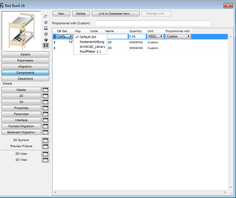
Click New to create a component.
DB Set: Select Database from this pop-up menu.
Key: Select one of the Keys from this pop-up menu.
Note: This pop-up menu is only available if your loaded library contains Key description.
Code: Define a Code for new Components or modify the Code of a selected one in this box.
Quantity: Define the Quantity for new Components or modify the Quantity of a selected one in this box.
Unit: Select one of the predefined Units from this pop-up menu.
Note: This pop-up menu is only available if your loaded library contains Unit description.
Proportional with: Select one of the predefined GDL expressions from this pop-up menu, or select the Custom button and enter any GDL expression in the long edit box above.
For details about Component Editing, see the ArchiCAD Calculation Guide.
Click this button to display the Descriptors of the current GDL Object in the editing area. Descriptors define the object’s composition for use in listing and calculation features.
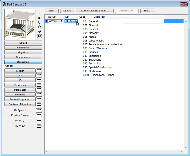
Click New to create a descriptor.
Link to Database Item: Click this button to link a Component or Descriptor to an external database residing in the selected databases of the loaded Library. While a Component or Descriptor is linked to the selected database, it cannot be edited. To modify it, click the Remove Link to Database button to unlink the Component or Descriptor.
Change Link: Click this to re-define an existing link to another external database
Text: Click this button to open the Descriptor Full Text dialog box displaying the whole Descriptor text.
Short Text: Enter Short Text for a new Descriptor in this box.
For details about Descriptor Editing, see the ArchiCAD Calculation Guide.
These buttons allow you to program your GDL Object. If you click the button itself, editing will take place inside the Master Window, while clicking the window icon next to the script’s name will open a separate window for entering or modifying the script.
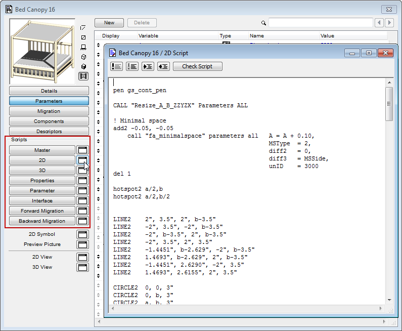
•The Master Script will be executed each time any of the other scripts are executed. The primary benefit of this script is that you can globally define variables or operations, or access external data before executing other Scripts.
•In the 2D Script window, you can create a parametric 2D symbol using the transformations and elements available for the two-dimensional space in GDL. This script will be used to generate the 2D Full View of the Object.
•In the 3D Script window, you can find and edit the 3D description of the GDL Object. The script will be used to generate the 3D View of the Object.
•With the Property Script, you can attach descriptions and technical data to the Object using its variables and the related GDL commands and expressions. Component quantities (weight, price, paint, etc.) can be calculated according to the expressions in the Properties Script and included in the lists. To use the custom Properties Script as the default in the element’s settings dialog box, click the Set as Default button at the top of the screen.
Note: When there is a Property Script defined, the listing commands will use this script, even if you previously created Components and Descriptors in the corresponding sections of the dialog box.
•Using the Parameter Script, you can define the choices available as a value of a given parameter. For example, you can restrict the choice of the surface of a table top to wooden surfaces, or define the different panel styles of a given door by their name.
•The Interface Script allows you to define a custom user interface for your GDL Objects, including the graphic explanation of additional parameters. If an Interface Script exists, the settings dialog box of the given library part will include a Custom Settings panel. To use the custom Interface Script as the default in the element’s settings dialog box, click the Set as Default button at the top of the screen.
•Forward/Backward Migration Scripts: Click the Forward Migration or Backward Migration buttons to define how to migrate the parameters of an old instance forward to the current open element (or backward to an older element).
At the top of all script windows, some commonly used functions are available in the form of buttons.
•Clicking the first button transforms selected lines into comments, that is, lines that will not be executed in the script. Comments are identified by an exclamation mark at the beginning of the line.
Note: You can select more than one line.
•The second button has the opposite effect: clicking it will transform any selected comments into executable lines.
•Clicking the third or fourth button will format the script window by tabulating selected paragraphs left or right.
•The last button checks the GDL Script of the active window.
Note: When you are working in a Script window, all of these functions are also available as menu commands from the Edit menu, along with other special script window editing commands.
Note: The Property, Interface and Parameter Script editing windows also include a Preview button to show a preview of the custom script.
Clicking the 2D Symbol item opens a new editing window from the Master Window.
Each GDL Object you place in your Project is shown on the plan by a 2D Symbol. You can edit an existing symbol or create a new one with the standard ArchiCAD selection and 2D tools: Arrow, Marquee, Text, Fill, Line, Arc/Circle, Spline and Hotspot. You can also paste elements from the 3D Window here.
The final symbol that appears on the Floor Plan will be created from the elements of this window and the 2D Script, if there is one.
To see the fragments of the 2D Symbol, select the 2D Symbol button, then go to Options > Element Attributes > Layer settings. The appearing list window shows the fragments of the 2D Symbol: these are useful for organizing the graphic elements that compose the plan symbol of the Library Part.
To toggle the visibility of layers of the object’s 2D Symbol, open the 2D Symbol window and click Ctrl+L (the shortcut for Layer Settings). The specialized Layer Settings window opens, which affects this window (the 2D Symbol window) only.
Click any fragment to show/hide it, or use the Show All/Hide All buttons.
Note: Fragments that are hidden are not available for storing new graphic elements. If you select a hidden Fragment in the dialog box of the Tool you are using for editing the symbol, you will get a warning asking you to change your selection or Show the selected Fragment.
Fragments are especially also for letting you easily replicate parts of the Symbol. You can draw a figure in the 2D Script Window with the various graphic tools, and refer to it by its Fragment number in a GDL 2D Script that incorporates the figure in the final symbol in a variety of rotated and translated positions.
To set which Fragment you are drawing in when editing the 2D Script Window, choose a number from the Layers pop-up in the settings dialog box of the Tool you are using.
In the Preview Picture window, you can attach characteristic graphical information to a GDL Object. The graphic does not affect the Object’s behavior or appearance in any way. This preview is displayed as the default representation of your Object in its tool settings dialog box, as well as next to library objects listed in a browsing window.
To generate the preview of a new Object:
1.Place the Object in the project.
2.Select the object and open the 3D Window to see this selection.
3.Go to View > 3D View Options > 3D Projection Settings. Choose a projection type and set up a view angle that show the typical features of your Object. Click OK.
4.Go to View > 3D View Options > 3D Window Settings. Set the window’s height and width to the same value to obtain a square shaped window.
5.Choose Document > Creative Imaging > PhotoRendering Settings. Define a pixel size that you will be able to insert in the preview without any distortion, and choose a neutral background for the Object (for example, white color for both the Sky and the Ground).
6.With the Object still selected, choose Document > Creative Imaging > PhotoRender Projection. A Model Picture is generated.
7.Choose Edit > Select All, then Edit > Copy.
8.Go back to the Floor Plan. With the Object still selected, choose File > Libraries and Objects > Open Object. This will open the Master Window of the selected Object.
9.Click the Preview Picture icon to open the corresponding window, then choose Edit > Paste.
10.Save the GDL Object.
You can also paste other data from the clipboard, for example a photograph of the real-life object.
Check Object’s 2D and 3D Views
At bottom left, the two view buttons allow you to open the corresponding views of the GDL Object:
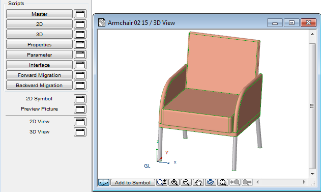
The 2D View window allows you to check the symbol that will be shown on the Floor Plan.
If there is a 2D Script defined, the 2D View will be calculated according to the script, even if the 2D Symbol window contains drawing elements. However, the 2D Script can refer to 2D Symbol Fragments.
To exit 2D symbol editing, close the symbol editing window or choose a different window, either from the Master Window, or from the Window menu.
In this window you can see the 3D view of the GDL Object converted from the 3D Script that refers to the current Parameter values. The viewpoint and other aspects are controlled using the View > 3D View Options > 3D Window Settings dialog box or the 3D Navigation Palette.
When closing the master window, a prompt warns you to save changes. All the components of your item will be saved with it.
You can also save your item using the Save or Save as commands from any of the library item’s windows. (From the 3D View, you can only save the image using Save as.) After saving, you can choose the View > Refresh > Rebuild command for the Floor Plan or 3D window to view the modified GDL Object.
If you close the Master Window of a GDL Object (Library Part), all of the other windows of the Object will also be closed. You will be prompted to save changes, if any.
The 2D symbol and the 3D description are automatically linked to each other in the GDL Object. There are no built-in safeguards against geometric incompatibilities between the two components. The most common incompatibility error occurs when the 2D symbol and the 3D shape have different positions or orientations with respect to the origin.
To avoid this problem, follow these steps:
1.Activate the 3D View of the GDL Object.
2.Choose Top View in View > 3D View Options > 3D Projections Settings > Parallel Projections, and set the angle to 270°.
3.Choose Edit > Select All, then Edit > Copy. Activate the GDL Object’s 2D Symbol window and choose Edit > Paste. This will place the top view of the object (as a wireframe or hidden line) into the symbol window. It should match the dimensions and position of the 2D symbol.
4.Choose Undo once you have verified that the symbol matches the 3D view. This will remove the 3D lines.
You can use this feature to have ArchiCAD create the 2D symbol for you. You will only need to add additional hotspots, line types, etc. The procedure is the same for Doors and Windows, with the following modifications:
•Choose Side View instead of Top View (the angle should still be 270°).
•A mirrored view will be placed. Select the placed lines and mirror them across the reference line of the wall.
Note: When you place a wireframe view, redundant lines are removed. Using Hidden Lines (analytic) will give you an accurate view, but underlying lines will be hidden.
You can also ensure compatibility between the 2D plan symbol and the 3D model of a GDL Object by writing a parametric description in GDL for the symbol.