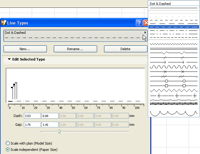
Use the Options > Element Attributes > Line Types command to open this dialog box.
For general information on Line-type elements, see Lines.
Choose a predefined Line Type from the pop-up list at the top of the dialog box. The first one in the list is a solid line; this is not editable.
The next set of lines in the list is dotted/dashed lines; these are editable.
For more information, see Line Edit Selected Type Panel.
The rest of the lines in the list are symbol-type lines; these are also editable.
For more information, see Line Edit Selected Type Panel (Symbol).
To create a new line type:
New: Click this button to create a new line type. In the resulting dialog box, choose one of the following options:
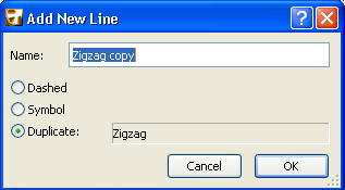
•Dashed: Use this option to create a line type based on a dashed line.
•Symbol: Use this option to create a line type based on a customized stencil of 2D drawing elements copied from an ArchiCAD window.
•Duplicate: Use this option to create a new line type by duplicating the selected line type under a new name and editing its properties.
Rename: Click this button to rename the currently selected line type.
Delete:
See Delete and Replace Attributes in a Model.
Note: The basic line types (Solid, Dashed, Dotted and Dense Dotted) cannot be deleted.
In this field, you will graphically edit the first component of the new or selected dashed line. The black and white flags represent sections of the dashed line.
Each black flag represents the end of a dash in the line, the length of which can be edited either by dragging the flag in a horizontal direction, or by editing its value in the Dash edit fields. The little white flags represent the gap between each dash section, and can be edited similarly. The values in the numerical input boxes are given in the respective measurement standards defined in Options > Project Preferences > Working Units.
Line Edit Selected Type Panel (Symbol)
To create a new symbolic line type, first draw the stencil on the Floor Plan or in another window, using Lines, Arcs and Hotspots. Select all stencil components, then choose Edit > Copy.
Choose Options > Element Attributes > Line Types.
Click New. From the Add New Line dialog box, select the Symbol option and click OK.
From the Line Types dialog box, click Paste line components under the graphic editing section.
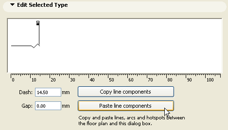
The previously captured line component will appear in the graphic editing Window. You may edit the scale of both line component and the gap between each component, by either dragging the little flags in the window or editing the numeric values underneath. The line component will be scaled as a whole. Modifications in size are reflected in real time by the change of the values in the numerical editing boxes.
Notes: Only Arcs, Lines and Hotspots may be used in the definition of symbolic lines. If the selection of components copied from the ArchiCAD window includes splines, fills, text or other elements, these will not be pasted into the Line Types dialog box. The bounding box of pasted graphics will be centered on the centerline of the Symbol line. If the Project Origin was located within the bounding box of the copied elements, it will be used for alignment.
Regular Copy-Paste operations do not function in this dialog box.
If you wish to change a symbolic line after the original components have been deleted from the Floor Plan, select the line to be edited within the Line types dialog box, and press the Copy line components button. Then paste these components on the Floor Plan, where you can edit them.
The appearance of the lines on the screen, printer or plotter depends on the following options:
•Scale with plan (Model size): Use this option to ensure that the current Line type will be displayed at the same scale as the model on every output.
Note: Avoid editing a scaled line type if the project scale is different than that of the line type, as it will be distorted.
•Scale-independent: Use this option to display, plot and print the current Line type definition at a fixed size, regardless of output scale.