To open the Profile Manager, do one of the following:
•Choose Design > Complex Profiles > Profile Manager
•Choose Options > Element Attributes > Profile Manager
•Select an existing Complex Profile Element, then click Edit Selected Complex Profile from the context menu.
For general information on this feature, see Creating or Editing a Complex Profile Element.
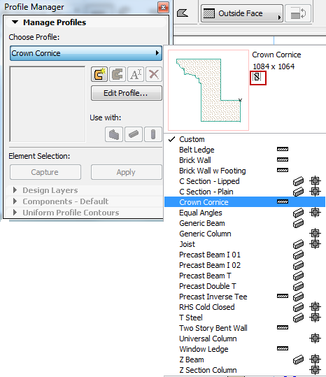
Manage Profiles Panel
Choose profile: Choose a profile from the pop-up list if you wish to duplicate, edit or rename an existing profile.
•New: Click this button to create a new profile: give it a name in the appearing dialog.
•Duplicate: Click this button to create a new profile by duplicating the selected profile under a new name (give it a name in the appearing dialog), then edit its properties.
•Rename: Click this button to rename the currently selected profile.
•Delete: Click this button to remove the selected profile from the project.
See Delete and Replace Attributes in a Model.
•Capture: If a Wall/Column/Beam element is selected in the active model window, click this button to capture the element in the Profile Editor window as a new profile element.
•Apply: If a Wall/Column/Beam element is selected in the active model window, click this button to apply the Profile that is currently chosen or under construction in the Profile Manager dialog box to the selected element.
In Profile Manager, the Use with buttons, like those in other Attribute Settings dialog boxes, determine which ArchiCAD tools can be used to place the current profile.
Design Layers contains layer settings that apply to the Profile Editor window only. (This panel is active only if the Profile Editor is open.)
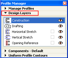
The layer of the active tool will be highlighted.
The show/hide parameters for Design Layers affect the Profile Editor window only.
Construction: Active if you are using the fill or hotspot tool to create a profile element. Click the eye icon to show/hide the fill (hotspot) elements in the Profile Editor window. All items drawn on the Construction layer will be saved as part of the profile.
Drafting: Active if you are using any other drafting tool. These elements will not be part of the saved profile element. Click the eye icon to show/hide the drafting elements in this window.
Items drawn on the Drafting layer will be saved as part of the profile attribute, but they will not be visible in the placed profile.
Note: Dimension elements placed in the Profile Editor window are not saved as part of the attribute; they are for drafting purposes only.
Horizontal/Vertical Stretch: An optional attribute of the profile. If you do not switch it on, you will not be able to stretch or resize the cross-section of the resulting profile once you place it on the plan.
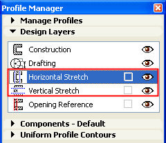
•Check the boxes to switch on the stretch parameter if you wish the final profile element to be stretchable in the horizontal and/or vertical directions.
•Click the eye icon to show/hide the stretch handle(s) in this window.
•Use the regular editing techniques in this window to move the stretch handles to the right position on the profile element.
If Horizontal/Vertical Stretch is switched on, the Profile Editor window displays dashed lines indicating the plane that can be stretched. Within the Profile Editor window, you can move these lines like any other drawing element to any part of the profile; these will serve as the stretch “handles” of the resulting profile element after it is placed in the model.
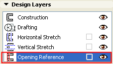
•Check this box if you want to set a reference line for the placement of openings in the placed profile element. The Profile Editor window will display a line representing the reference line at which doors/windows will be placed, once you place the profile wall on the plan.
•Click the eye icon to show/hide the Opening Reference line in the Profile Editor window.
•Edit this reference line in the Profile Editor window to ensure the right position for wall openings.
•If necessary, edit the line, like any other line, to conform to the shape of the profile so that openings will be in the right place.
If you do not switch on Opening Reference, doors/windows will be placed along the profile element’s bounding box.
Select a component (represented by a fill or line) in the Profile Editor window.
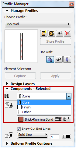
In the Components panel of Profile Editor, edit the following parameters:
•Component Type: Click this pop-up to define the selected component as either Core, Finish or Other. This definition will affect the Partial Structure Display of the complex element.
See details at Partial Structure Display.
•Surface: If the Use Building Material box is checked, then the selected component will use the Building Material’s surface. To use a different surface for this component, uncheck the box, then choose a new surface from the pop-up.
•Cut End Line Type: Define the Line Type and pen of the selected Profile line component. This line type and pen are used for end lines when the element is displayed with “Cut Only.”
(If you don’t want to display these lines, uncheck the Show Cut End Lines box.)
Profile - Uniform Contours Panel
This section of the dialog box lets you apply uniform line types and pen colors to cut lines and to all separator lines at once, for display in Section and Floor Plan. (This panel is active only if the Profile Editor is open.)
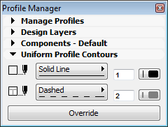
Cut lines: Choose a uniform line type and pen color for all of the cut lines (outer lines) of the profile element.
Separators: Choose a uniform line type and pen color for all of the separator lines (inner lines) of the profile element.
Override: Click this button to apply the Cut Lines and Separator settings to the respective lines in the Profile Editor window. These uniform settings will override all individual line settings.
Note: Lines that separate two fills having the same Building Material will be eliminated; the two fills will be merged into one.