

Use the View > 3D View Options > 3D Window Settings command to open this dialog box.
3D Engine: Select from the list of available 3D engines.
•OpenGL: This is the default engine and recommended if your video display card supports OpenGL. However, some effects, for example vectorial 3D hatching and the option to save the contents of the 3D window as a vectorial 2D drawing, are not available with OpenGL.
Options button: Click here for Open GL Options.
•Choose the Internal Engine to use effects like vectorial 3D hatching and to have the option of saving the contents of the 3D window as a vectorial 2D drawing.
See also 3D Engines.
Mode: Select from the list of model formats to be displayed in 3D: Wireframe, Hidden Line or Shading. These modes differ in the amount of detail they show.
Note: If you are using the OpenGL engine, there is no Hidden Line mode.
Note: If you have defined a Layer as Wireframe, its elements will always appear in Wireframe mode, even if you have chosen another 3D view mode here.
Both the 3D Engines and the 3D display modes are also accessible from View > 3D View Options.
Methods: Define the processing methods for the 3D Window if you are in Hidden Line or Shaded 3D Modes. (If you are using the OpenGL 3D engine, only the “Contours” setting is available here.)
•Hidden Line Mode/ Shaded Mode: Click these pop-up fields to select Analytic (slower but more sophisticated) or Raster (faster but less sophisticated) computational methods for generating images in the 3D Window.
•accurate surface polygons,
•zoomable image, resolution-independent,
•3D hatching and 3D shadows can be applied,
•can be saved in several formats,
•plottable at any size with HP DesignJet raster plotters.
•bitmapped image,
•no effects are available, cannot be plotted.
Contours: Click this pop-up field to define whether contours will be visible in Shaded images. Contours are lines showing the edges of model elements.
•Off: Choose this to ensure that no contours are visible in Shaded images.
•The Draft option produces a fast result, but it doesn’t eliminate all the lines that the Hidden Line Analytic method would.
•The Best option produces a perfect result, but it may be rather slow for large and complex 3D models.
Vertical Raster Strips: Enter a value here to determine the number of vertical strips used to raster Shaded or Hidden Line models.
Hint: More strips provide a more realistic image, but take longer to process. For fast but clean images, select 3 to 10 vertical strips, depending on your screen size. Do not go beyond 50 strips, as this will usually not enhance the image any more, but will take more time to calculate. Beyond a limit, the only way to get better images is by using the Analytic Hidden Line, the Analytic Shading or PhotoRendering methods.
Effects: Use the controls in this section to specify the use of 3D hatching, shadow-casting and transparency. (If you are using the OpenGL 3D engine, 3D vectorial hatching is not relevant here.)
•Vectorial 3D Hatching: Click this pop-up field to define whether Vectorial Hatch patterns are used in Analytic Hidden Line and Shaded images, provided that you have already selected a 3D Hatching in the Surfaces dialog box for any surface you are using in your Project.
For more information, see Surfaces.
Note: Vectorial 3D Hatching is also available for Section/Elevation/IE Windows and for 3D Documents, but this setting has to be made individually in each Section/Elevation/IE and 3D Document Settings dialog box. The choices made in the 3D Window Settings dialog box have no effect on Section/Elevation/IE or 3D Document windows.
Transparency in Shading: Turn this setting On to produce transparent views of elements that have the appropriate Surfaces setting when generating a shaded view. Below, the same glass wall appears with Transparency in Shading Off and On.
When saving a view for publication, the Transparency in Shading setting will be saved with the view.
Note: When used with the Internal Engine, Transparency in Shading is not effective with Postscript printers.
•Sun Shadows: Click this pop-up field to enable ArchiCAD’s shadow-casting capability (choose “On”) and to specify whether shadow contours should be shown in the 3D Window. (Click On with Contours to show them). Click Off to hide shadows.)
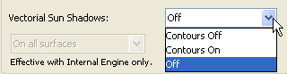
If you have turned Sun Shadows on, use the pop-up field below to define where Sun Shadows are generated:
•on all surfaces, or
•on a single horizontal plane only. (This option is useful for shadow studies in top view.) If you choose this option, enter a value here to specify the absolute elevation of the horizontal plane on which the Vectorial Shadows will be generated.
The Sun Shadow option is also effective for Wireframe, Analytic Hidden Line and Shaded images.
Display: Use the controls in this section to define characteristics of the 3D Window.
Window Size in Pixels: Enter the horizontal and vertical size of the 3D Window here.
•Keep Proportions: Check this box to always have proportions maintained.
Line Weight: Define lineweights for Wireframe and Hidden Line modes here. This option is available for the Internal Engine only.
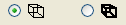
•Click the left button to use single-pixel lineweights in Wireframe and Hidden Line display modes.
•Click the right button to use double-pixel lineweights.
Background: Define the background color of the 3D Window here.
•Single Color: Click this button to apply the color in the box on the right as the background color of the 3D Window. Double-click the color field to choose another color from the pop-up palette.
•As in PhotoRendering: Click this button to use the background specified in PhotoRendering Settings.
See also CineRender Basic Settings: Background Panel.
GDL Object Hotspots: Use these buttons to enable or disable editable Object hotspots in the 3D window.
•Enable 2D Hotspots: Choose this to enable Hotspots defined for 2D editing. (This will give you more editing points.)
•Show 3D Hotspots only: Choose this to enable 3D editing by dragging pre-defined Hotspots.
Note: If the GDL Object has no 3D hotspots at all, the 2D hotspots will be always displayed, as well as their copies projected to the zzyzx height value, provided that such a parameter has been defined for the object.