
The Camera tool is used to define the settings of individual perspective views and the Fly-Through path.
For more information, see Cameras.
The Camera Settings palette and the Floor Plan are simultaneously active, so you can alter the settings, the camera locations and orientations without repeatedly opening and closing the window.
The Sun dialog box is also accessible from the Camera Settings dialog box.
See Sun.
Click New to add a new path to the project to start a new collection of 3D projections. The Add New Path dialog box opens. Here you can:
•Enter the name of the new Path.
•Add Copy of Current Path: Check this box to duplicate the current set of projections while you define a new one.
Click Rename to rename the current path, then type the new name in the dialog box and click OK or select a path in the pop-up list.
If you have already defined one or more camera paths, choose the desired camera path from the pop-up menu.
Click Delete to delete the current path. The path name will be removed from the list and all its cameras will be deleted.
Camera: To select a particular camera from the current camera path, use the up/down arrows to scroll through the camera numbers, or enter the camera number from the keyboard.
Wait here: This number refers to the number of still frames (time units) during which the fly-through motion will remain frozen at the given camera before moving on to the next one.
Enter the number of still frames to be included in the Fly-Through Path for the selected Camera.
Click Smooth Path at Cameras to smooth the path between the selected cameras. This action smooths the Bézier camera path and restore the tangent line defining the path to its original position if you have modified it.
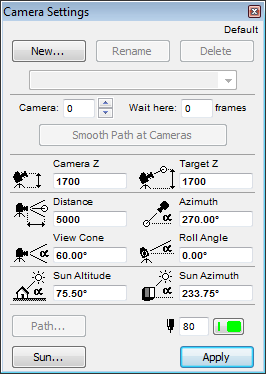
Enter parameter values for the current camera:
Camera Z: Enter a value to specify Camera height from Project Zero.
Target Z: Enter a value to specify Target height from Project Zero.
Distance: Enter a value to specify the horizontal viewing distance between Camera and Target.
Azimuth: Enter a value to specify Camera Azimuth to Target.
View Cone: Enter a value to specify the opening angle of the Camera View Cone.
Roll Angle: Enter a value here to specify Camera Roll Angle.
Sun Altitude: Enter a value here to specify Sun Altitude used in shaded or rendered images.
Sun Azimuth: Enter a value here to specify Sun Azimuth used in shaded or rendered images.
Note: If you adjust the Project North value, the sun azimuth value here will change accordingly.
See also Project North.
Use the Pencolor/Penweight controls to specify a pen color for the selected camera. (To modify the color of the path line, use the Path button for opening the Path Options dialog box.)
Sun: Click this button to access the Sun dialog box.
For details, see Sun dialog box.
Path Name: rename the current Path if desired.
Motion Controls
Camera: Choose radio buttons to set the shape of the Camera Path:
•Polygon: Click this button to place In-between Frames along a straight line between Key Frames (Polygonal Animation Path).
•Bézier: Click this button to place in-between Frames along a Bézier curve between Key Frames (Bézier Animation Path).
Note: Bézier makes for smoother animations, while Polygon paths are somewhat jumpier.
•Open: Click this button for an open-ended Path Loop.
Hint: The first and last Key Frames of an Animation Path can also be coincident.
•Closed: Click this button for a continuous-loop Path.
Hint: Use this to create smooth endless loop Animations.
The Target option defines the shape of the target point path during the Fly-Through animation.
•Polygon: This option will place the target points of the in-between frames on the straight line that connects the two consecutive key target points.
•Smooth: This option will place Targets along a smooth curve between Key Targets.
Note: Smooth is available only if you have specified Bézier for the camera motion.
Hint: Use Polygon target motion if your camera moves a lot but the target stands stills or moves just a little. This is the case when you fly around a building but keep the same spot in sight. In other cases, try both methods to see which one suits you better.
Motion Resolution
Each 3D Projection you add to the path is considered a keyframe. ArchiCAD can interpolate between keyframes to create In-between views which produce a smoother animation.
Cameras on the path: Shows the total number of Cameras in the current Polygonal or closed loop Bézier Path.
In-between frames: Enter the number of in-between Frames between each Key Frame here.
A larger number of in-between frames makes a smoother animation Path, but uses more memory and hard disk storage space.
Total frames: Shows the total number of Key and in-between Frames.
Display Options
Choose the format in which to display the frames of the current Path: (Cameras are never displayed in printed output.)
•None: Since Cameras cannot be assigned to Layers, choosing None in Display Options here is the only way you can hide them on the Floor Plan.
•Camera only
•Camera & Path
•Everything: the location of the in-between frames will also be shown.
Choose which frames to display:
•Click the Cameras radio button to specify a range of keyframes to be displayed.
•Click All to display all frames of the path
This setting will be used as a default in the Create Fly-Through dialog box: only the visible part of the path will be processed.
Enter a Pencolor for the line of the camera path.
For more information, see Fly-Through.
Click OK to confirm Path Options and return to the Camera Settings dialog.