For a description of generic settings common to all tools in the Toolbox, see Working in Tool Settings Dialog Boxes.
For details, see Fills.
If You Are Editing the Fill Component of a Profile
If you are editing a selected fill component of a Profile attribute, the only available controls are Fill outline on/off, cut line type and color, and Fill type selection (the available Fills here represent Building Materials for the profile you are editing).
See Creating or Editing a Complex Profile Element.
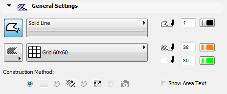
This panel controls the appearance of the Fill in the Floor Plan. These Fill settings will also be used if you draw a Fill in a Section/Elevation/IE or Detail/Worksheet window.
•Push the button if you want your Fill to have an outline.

•Choose a Line Type and an outline color from the Line Type and Pen Color pop-up palettes.
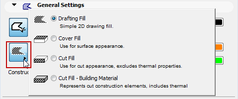
•Choose the fill type that will be used to display the Fill.
The Fills available here are all simple Fill types (composite structures are not available); and all are defined as Drafting fills. (set in Options > Element Attributes > Fill Types).
•Choose a color for the Fill pattern.
•Choose a color for the Fill background.
For the fill background, you can also choose the transparent option or the Window Background color (located at the end of the Pen Color palette).

Note: The fill background color you may be overridden by project-wide settings for Model View Options, in the Override Fill Display panel.
See also Model View Options Override Fill Display.
Click the button to the left of the Fill pattern pop-up to choose a Fill Category for this Fill.
For more information, see Fill Categories.
The Show Area Text checkbox allows you to show an associative area text with the Fill. If this box is checked, you will place (as part of the fill drafting process) a dimension-text element displaying the Fill’s area on the plan.
Note: To format Area Text, use the Dimension Text Settings dialog box.
Click one of the radio buttons to set the orientation of the fill’s vectorial hatching (if any) or symbol fill pattern.
Note: Vectorial hatching is displayed only if you have switched to in View > On-Screen View Options > Vectorial Hatching.
•If you choose Project Origin, the pattern will start at the Origin and the part of the pattern that falls within the Fill’s boundary will be displayed.
•If you choose Fill Origin, then after you draw the fill polygon, the fill handle icon appears. Use this to draw the desired fill orientation vector. Then click to place the vectorial fill.
•If you choose Use Distorted Fill, the fill will include two fill handles that can be manipulated to achieve a “distorted” effect to simulate the real geometric situation of the fill components.
For examples of each option, see Fill Orientation Methods.
A fourth option is the Radial Distorted Fill construction method, with which you can graphically adjust the vector’s radial distortion. This is available only for a selected symbol Fill and only if:
•the symbol fill was used as a skin of a composite structure; and
•the skin’s Fill Orientation was defined as Fit to Skin in the Composite Structures dialog box; and
•you have selected this symbol fill after exploding a curved composite wall.
See Explode into Current View.
Note: The use of many radial distorted fills in your project may decrease project performance.
Fill Tags and Categories Panel
ID: Type an ID in this box for tracking this element in Quantity Calculations.
The ID field serves to identify and group elements in list views. The text string within this field cannot exceed 15 characters. Any character can be used.
If a number is included anywhere in the 15 characters, ArchiCAD will add one to this number for each new element drawn, provided that the Auto ID Increase checkbox is enabled in the Options > Work Environment > More Options dialog box. Each new element will have a unique ID.
If elements are duplicated or multiplied, the IDs of the replicas will remain the same as those of the originals.
If you paste elements into a Project, you may have elements with conflicting IDs. ArchiCAD does not automatically exclude ID conflicts. It is up to the user to designate different IDs for elements that may be in conflict.
IDs can be customized both before creating elements and after selecting a number of existing ones, by using Document > Schedules and Lists > Element ID Manager.
For more information, see ID Management.
Note: All construction elements also have a globally unique, automatically generated ID which is conserved throughout the life of the Project. You can use this identifier for labeling or in lists.
Fill Listing and Labeling Panel
See Listing and Labeling Panels.
For Fills only, some additional controls are also available:
Check the Subtract from Zones checkbox to subtract default or selected Fill elements from the Zones.
Type a number (1-100) in the percentage field to define the percentage of the Fill element’s area that you want to subtract from the Zones in percentage.
Fill Tags and Categories Panel