The Editing Plane is shown by default in the 3D window. To hide it, use the toggle at View > Editing Plane Display.
Note: Regardless of the state of this toggle, the Editing Plane will be temporarily displayed whenever necessary: for example, after you choose a plane for Ruled Shell input.
Display Editing Plane During Editing Operations Only
If the Editing Plane Display toggle is on (View > Editing Plane Display) - and it is on by default - you can still limit its appearance using this checkbox, at Options > Work Environment > On-Screen Options.
If you check this box, the Editing Plane will appear only during the time you are actively editing in the 3D window (provided that the “Editing Plane Display” toggle is turned on.) When you are done with the operation, the Editing Plane disappears.
3D Editing Plane: Color and Grid
The 3D Editing Plane has a grid system that is the same as the one on the Floor Plan, and reflects the X-Y coordinate plane, so you can use the Tracker to numerically input element geometry.
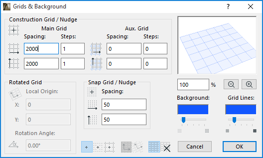
As with the 2D grid, use View > Grid and Editing Plane Options > Grids and Background to set up your grid and color preferences (the 3D window must be active to set editing plane options). As in the 2D window, you can rotate the grid, and use Grid Snap, Snap Guides and Guide Lines to aid in element placement.

See also Grids & Background Dialog Box.
As you zoom in within the 3D Window, you will notice that the Editing Plane’s additional automatic gridlines appear on the Editing Plane. You cannot snap to these, but they can help achieve accurate input.