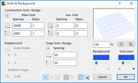
Use the View > Grid and Editing Plane Options > Grids & Background command to open this dialog box.
The Grid is visible in 2D and 3D Windows.
For general information on this feature, see Grid System.
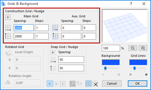
Construction Grid/Nudge
You can set separate Spacing and Steps values for the Main Grid and the Aux. (Auxiliary) Grid.

Note: All the values in this dialog box are based on the current measurement units defined in Options > Project Preferences > Working Units.
Spacing: Enter values to define the horizontal and vertical distances between grid lines.
These Spacing values will also define the larger Nudge distance: use the Nudge shortcut to move elements by a slight predefined factor. (use Alt + Shift + an arrow key to move the element left, right, up or down).
See Nudging Elements.
Steps: Enter values to define the number of times to display the Main grid line before displaying the Auxiliary grid line, in both the horizontal and vertical directions. If the “Steps” value for any of these grid lines is 0, those lines will not be displayed.
In the example above, you will display one main grid line (spacing 2000), followed by two Auxiliary grid lines (spacing 1000); then the pattern repeats.
The sample window on the right displays a preview of the Construction grid (both the Main grid lines and Auxiliary grid lines). Use the percentage and Zoom In/Zoom Out controls (below the preview window) for zooming in the preview window.
Note: The grid is automatically hidden if it would be too dense on the screen, that is, if the smallest distance between two adjacent grid lines would be smaller than 3 pixels.
Rotated Grid
Local Origin: Specify X and Y values to specify a local origin that is different from the Project Origin.
Rotation Angle: Enter a Rotation Angle to define the Rotated Grid.
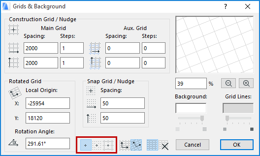
To enable the Rotated Grid, click the Rotated Grid button at the bottom of the Grids & Background dialog box. (The same command appears in the Coordinate Palette and in View > Grid Options.)
Snap Grid
Spacing: Enter a value to define the intervals (horizontal and vertical directions) to which the cursor will snap when Snap Grid is activated.
See Grid Snap Status below.
See also Grid Snap Function.
These Spacing values will also define the smaller Nudge distance: use the Nudge shortcut to move elements by a slight predefined factor. (use Shift + an arrow key to move the element left, right, up or down).
See Nudging Elements.
Use the buttons to enable the Grid Snap function you want to use: No snap; Snap to Construction Grid; or Snap to Snap Grid. (The shortcut for this toggle is: Shift+S).

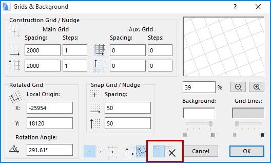
Grid Display ON/OFF
Click the appropriate icon at the bottom of this dialog box to switch Grid Display on or off.

Background: This field displays the color of the window background. Double-click the field to open the Set Color (on Mac: Color) dialog box to select a different color.
Grid Lines: Double-click the field to open the Set Color (on Mac: Color) dialog box to select a different color for the Grid Lines.
Note: The color you select here will also be used for the dimmed Project Origin when it is temporarily displaced.
The next two controls are available only if the 3D window is active.

Grid Background/Grid Opacity: Use the sliders to set the intensity of the grid background (editing plane) and the grid lines in the 3D window only.