
Set Slab parameters in Slab Settings.
See Slab Tool Settings.
New Slabs can be created in either the Floor Plan or the 3D Window.
Depending on the structure you choose for the Slab (either a basic or a composite slab), you have varying construction method options for the Slab Reference Plane:
See Slab Reference Plane.
Choose one of the three Slab Geometry Methods from the Info Box.
•With the first icon on the left, you can create a Polygonal Slab. Just like for Walls, the pet palette appears and allows you to draw straight and curved segments for the Slab’s outline.
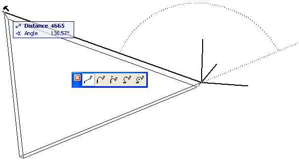
•The second and third icon allow you to create a Rectangular or a Rotated Rectangular Slab. The rectangle is defined by placing two opposing corner nodes. A rectangle Slab is always aligned orthogonally with the normal grid. The Rotated Rectangular method requires that you first define a rotation vector, then drag the cursor in a perpendicular direction to complete the slab.
Create a Composite Slab
You can apply or customize a composite structure for a Slab.
For more information, see Composite Structures and Assign a Composite Structure to a Wall, Slab, Roof or Shell.
(Remember that the model’s Partial Structure Display settings will affect the display of composite Slabs.)
See Partial Structure Display.
If the structure of the slab is a composite, then the slab’s thickness is defined in Options > Element Attributes > Composites, and equals the sum of the skins’ thicknesses.
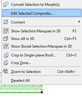
Note: You can edit a selected composite by accessing its settings from its context menu:
You have four options for the reference plane of a composite Slab: top of slab, bottom of slab; top of core, bottom of core.
See also Slab Reference Plane.