
Define Curtain Wall Input Plane in 3D Window
With the Curtain Wall tool active in the 3D window, the Info Box provides the following options for defining the Curtain Wall’s input plane:
Default: Use the default input plane in the 3D window, which is the same input plane - Project Zero or the User Origin - you use when working with any other tool in the 3D window.

Intelligent: Use one of the following “intelligent” methods to define an input plane by a series of clicks:
•Surface: Click any surface: the plane of the surface will be your input plane.
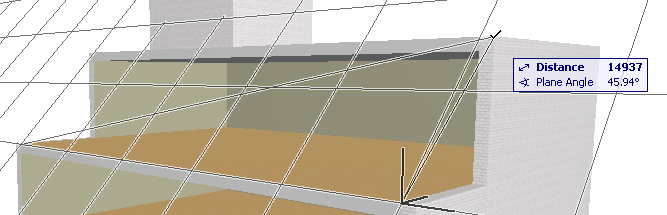
•Edge plus point: Click any edge (Mercedes cursor) to define a line.
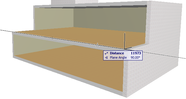
A plane appears on screen, rotating around the line as its axis. Then click a point (arrow cursor) to fix the input plane.
•Point plus edge: This is just the reverse of the method above. Click a point, then an edge to define the input plane.
•Three points: Click any three points to define the input plane.

Horizontal: Click on a point to place a horizontal input plane at that point.

Vertical: Click on a point to place a vertical input plane at that point.

Normal: Define a slanted input plane by defining a vector that is perpendicular (“normal”) to the desired plane.
1.Click two points to define the normal vector to the input plane, or
click on an edge to define the normal vector to the input plane.
2.Then click a point through which the input plane will run.
For an example, see Extrude Curtain Wall from a Slanted Input Plane.