Create a Single Flat Curtain Wall in the 3D Window
In the 3D window, the process is the same as in the Floor Plan. However, the feedback is different.
In the 3D window, the default Curtain Wall input plane is the same as the current 3D input plane (Project Zero, or the User Origin).
To define other input planes, see Define Curtain Wall Input Plane in 3D Window.
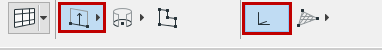
With the Curtain Wall tool active, choose the Polyline - Single geometry method and the Default Input Plane from the Info Box.
Click to begin drawing the Curtain Wall Reference Line. No matter where you click, the input plane is fixed, and indicated by a temporary grid. Any Reference Line you now draw will be placed on this input plane.
In our example:
Click at the two front corners of the building to define the Reference Line length. With the “Sun” cursor, click on either side of the Reference Line to define the outside of the Curtain Wall.
The Place Curtain Wall dialog box appears:
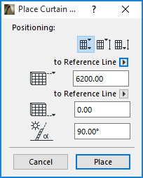
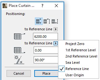
By default, both the top and the bottom height values are measured to the Reference Line, and the Curtain Wall will be perpendicular to the Input Plane, but you can choose a different reference level using the pop-up:
Note: The three icons in the Positioning part of the Place Curtain Wall dialog box give you three different methods for defining the Curtain Wall height.
For details, see Place Curtain Wall Dialog Box: Floor Plan and 3D Window.
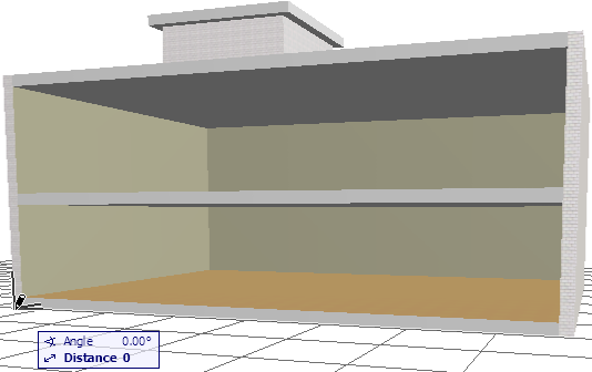
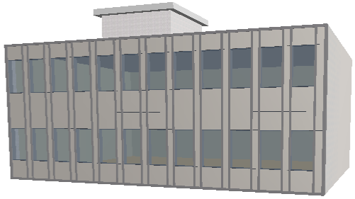
Click Place. View the result.
To edit the Curtain Wall’s individual Members, select the Curtain Wall and click the Edit button. (If you select the Curtain Wall in the Floor Plan or Section/Elevation, this is the “Edit in 3D” button.)