Draw Curtain Wall Boundary in the 3D Window
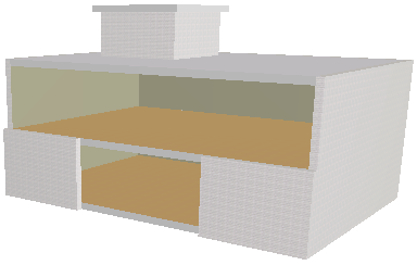
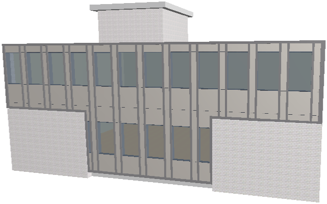
We start with the following building model. We will create a Curtain Wall whose Boundary runs along the opening on the building’s southern face. To do this, we will use the Boundary geometry method in the 3D Window.
In the 3D window, the default Curtain Wall input plane is the same as the current 3D input plane. However, you can use a different Input Plane to make input easier.
For more information, see Define Curtain Wall Input Plane in 3D Window.
In this example, we will use the “Intelligent” Plane Input to define the plane that is perpendicular to the slab.
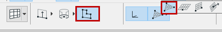
With the Curtain Wall tool active, choose the Boundary geometry method and the Intelligent Input Plane Method from the Info Box.
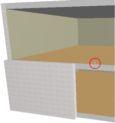
Now you must define the Input Plane by a series of clicks. Here, click the slab edge with the Mercedes cursor (indicating an edge) to define a line. As feedback, an input plane appears in the window, rotating (as you move the cursor) around the line you clicked.
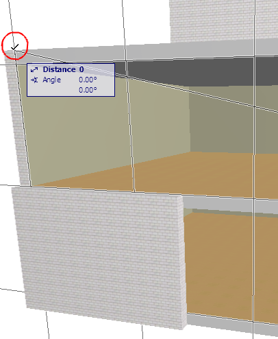
Next, click the upper corner of the building with the Arrow cursor to define the input plane’s final position.
Now click to begin drawing the desired Curtain Wall Boundary on the input plane, clicking at each node as when drawing any polyline.
Note: The Reference Line of this Curtain Wall is the first Boundary segment you draw.
Double-click or click with the Hammer cursor to close the polygon.
When the “Sun” cursor appears, click on the polygon surface: the outside of the Curtain Wall will face toward you.
View the result.
To edit the Curtain Wall’s individual Members, select the Curtain Wall and click the Edit button. (If you select the Curtain Wall in the Floor Plan or Section/Elevation, this is the “Edit in 3D” button.)