Note: The Coordinates Palette is not visible by default. To show it, choose its name from the Window > Palettes menu.
Use the context menu to display this palette in horizontal/vertical or extended/compact form.
From left to right, the Coordinates Palette contains the following controls:
•User Origin: Resets the zero point to a user-defined location. Click this button and place the Origin anywhere on the Floor Plan.
Note: To return the User Origin to the Project Origin, double-click the User Origin button.
For more information, see Origins.
•Set Rotated Grid: Click Rotated Grid button, then draw a vector on the Floor Plan to specify the angle of the rotated grid. Note: To return to the ‘normal’ grid, use the Grid Switch button.
•Switch Orthogonal/Rotated Grid: Select the Rotated Grid option to switch to the rotated grid or the Normal Grid option to switch to the horizontal/vertical grid.
•Grid Snap: Select one of these three options to control Grid Snapping:
-Grid Snapping OFF
-Snapping to the Snap Grid
-Snapping to the Construction Grid
For more information, see Grid Snap Function.
•Absolute/Relative: Switch the delta button ON to display and enter relative X and Y coordinates (for Cartesian coordinates) and radial/angle coordinates (for polar coordinates).
Absolute values show the horizontal, vertical, radial and angular distance of the cursor from the Project Origin or a User Origin but never from an Edit Origin.
Relative values show the horizontal, vertical, radial and angular position of the cursor relative either to the Project Origin, to a User Origin before any element is begun, or to an Edit Origin once a drafting or editing process is under way.
In general, viewing Absolute Cartesian and Relative Polar coordinates provides the most information, and is the most useful under normal circumstances.
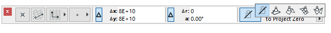
•Gravity: The Gravity icon and pop-up control allows you to determine how to place elements atop Slabs, Meshes, Shells and Roofs.
The Gravity icon can be set to either “ON” or “OFF.” The option you choose from the pop-up - Gravitate to Slab, Roof, Shell or Mesh - will function if the icon is set to “on.”
For more information, see Elevation.
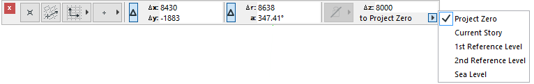
•Elevation: The “z” field in the Coordinates Palette displays the elevation at which elements will be placed. The pop-up lets you define the reference level from which this value should be measured: the Project Zero, the current Story (or in 3D, the User Origin), or one of the optional Reference Levels defined in Options > Project Preferences > Reference Levels.
See Reference Levels Preferences.