To open the Profile Manager, do one of the following:
•Choose Options > Complex Profiles > Profile Manager
•Choose Options > Element Attributes > Profile Manager
For general information on Complex Profiles, see Place a Wall/Column/Beam with a Complex Profile.
Apply Profile to Selected Element
If a Wall/Column/Beam element is selected in the active model window, click this button to apply the Profile that is currently chosen or under construction in the Profile Manager dialog box to the selected element.
Edit Existing Profile
To edit an existing profile, do one of the following:
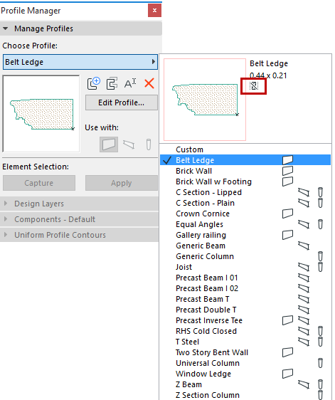
• From Profile Manager, choose a Profile from the pop-up:
Notice the icon that indicates whether the selected profile contains a core component, or not. (In this image, the icon indicates “No Core.”)
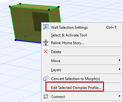
•From the model window, select an existing Complex Profile Element, then click Edit Selected Complex Profile from the context menu. The Profile Manager opens in the Profile Editor window:
Note:
•In Profile Editor, only 2D drawing tools are available to draw or edit the cross-section of the profile element.
•In Profile Editor, use the Scale setting from Quick Options to get a preview of what the profile will look like at a given Scale
Use the Fill tool to draw the cross-section of the complex profile, with the usual 2D techniques, to achieve the desired shape.
Define or Edit Profile Component Fill
Select a fill component from the Profile Editor window to edit it.
Your cross-sectional profile can contain multiple fill shapes (components); they will all be saved together as a single profile.
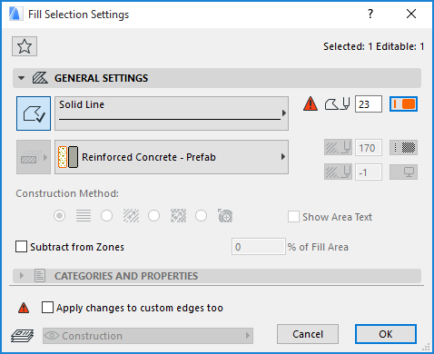
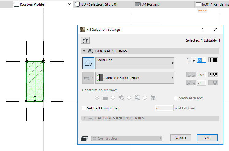
Use the Fill Tool to draw and edit the shape. In Fill Selection Settings, you can then assign its Building Material and set a cut line/pen (or turn it off).
You can customize any edge surface of a Profile element.
See Apply Custom Surface or Line to Profile Edge.
Profile Origin in Profile Editor Window
The Origin shown in the Profile Editor window is a significant reference point: if the complex element is a Wall, the origin represents the location of the Wall’s reference line. In case of a Column or Beam, the origin represents the location of the element’s axis. You cannot move this origin, but you can move the profile shape so that it correctly positioned with respect to the origin.
Only hotspots and shapes drawn with the Fill tool in the Profile Editor window will be part of the saved profile. Other 2D elements added to the Profile Editor window (lines, dimensioning, etc.) can be used as local drafting aids, but will have no effect on the final appearance of the complex profile when placed into the model. (These drafting aids are located on the “Drafting” Design Layer.)
Capture Selected Element for New Profile
To create a new profile using the shape of a selected element in the active model window, click the Capture button in the Profile Manager, or use Options > Complex Profiles > Capture Profile of Selection.
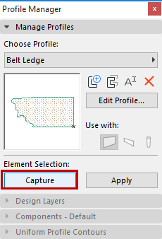
The new profile is called “Custom”.
Store Custom Profile
After editing a Custom profile in the Profile Editor window, make sure you click Store Profile to save your edits and name the new Profile, before closing the window.
Alternatively, click Apply to apply a one-off custom to a selected Wall, Beam or Column.
Note: Custom profiles are not directly assigned to elements from the Profile Manager, but locally stored in the element.
When you close the Profile Editor after modifying a Custom profile, no warnings will be given and changes are automatically stored within the “custom”.
However, to permanently store a custom, click “Store Profile:” a dialogue will appear to name and store the profile.
Store and Save Named Profile
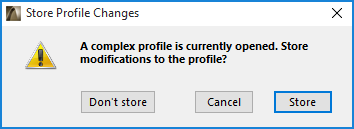
After you edit a named Profile, you are required to confirm and store these changes.
Do one of the following:
•Click the Store Profile button in the Profile Manager, or
•Switch to another profile and choose “Store” from the appearing dialogue.
In Profile Manager, the Use with buttons, like those in other Attribute Settings dialog boxes, determine which ARCHICAD tools can be used to place the current profile.
Manage Profiles
The four icons in the Manage Profiles panel enable you to create a new profile, or to duplicate, rename or delete it.
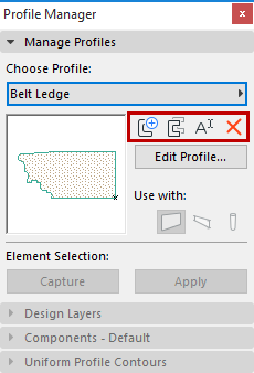
•New: Click this button to create a new profile: give it a name in the appearing dialog.
•Duplicate: Click this button to create a new profile by duplicating the selected profile under a new name (give it a name in the appearing dialog), then edit its properties.
•Rename: Click this button to rename the currently selected profile.
•Delete: Click this button to remove the selected profile from the project.
See Delete and Replace Attributes in a Model.
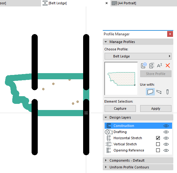
Design Layers contains layer settings that apply to the Profile Editor window only. (This panel is active only if the Profile Editor is open.)
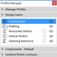
The layer of the active tool will be highlighted.
The show/hide parameters for Design Layers affect the Profile Editor window only.
Construction: Active if you are using the fill or hotspot tool to create a profile element. Click the eye icon to show/hide the fill (hotspot) elements in the Profile Editor window. All items drawn on the Construction layer will be saved as part of the profile.
Drafting: Active if you are using any other drafting tool. These elements will not be part of the saved profile element. Click the eye icon to show/hide the drafting elements in this window.
Items drawn on the Drafting layer will be saved as part of the profile attribute, but they will not be visible in the placed profile.
Note: Dimension elements placed in the Profile Editor window are not saved as part of the attribute; they are for drafting purposes only.
Horizontal/Vertical Stretch: An optional attribute of the profile. If you do not switch it on, you will not be able to stretch or resize the cross-section of the resulting profile once you place it on the plan.
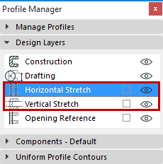
•Check the boxes to switch on the stretch parameter if you wish the final profile element to be stretchable in the horizontal and/or vertical directions.
•Click the eye icon to show/hide the stretch handle(s) in this window.
•Use the regular editing techniques in this window to move the stretch handles to the right position on the profile element.
If Horizontal/Vertical Stretch is switched on, the Profile Editor window displays dashed lines indicating the plane that can be stretched. Within the Profile Editor window, you can move these lines like any other drawing element to any part of the profile; these will serve as the stretch “handles” of the resulting profile element after it is placed in the model.
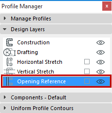
•Check this box if you want to set a reference line for the placement of openings in the placed profile element. The Profile Editor window will display a line representing the reference line at which doors/windows will be placed, once you place the profile wall on the plan.
•Click the eye icon to show/hide the Opening Reference line in the Profile Editor window.
•Edit this reference line in the Profile Editor window to ensure the right position for wall openings.
•If necessary, edit the line, like any other line, to conform to the shape of the profile so that openings will be in the right place.
If you do not switch on Opening Reference, doors/windows will be placed along the profile element’s bounding box.
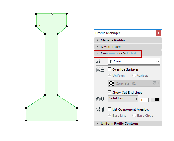
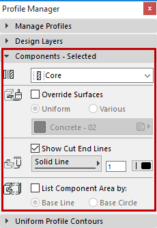
Use the Components Panel of Profile Manager to do the following:
•Define the Profile component’s structure definition (e.g. Core or Finish)
•Override the Profile component’s Building Material
•Set its end line type (or turn off cut end lines altogether)
•Define how to calculate Surface Area for this component in an Interactive Schedule of Components.
Select a component (represented by a fill or line) in the Profile Editor window.
Edit the following parameters:
•Component Type: Click this pop-up to define the selected component as either Core, Finish or Other. This definition will affect the Partial Structure Display of the complex element.
See details at Partial Structure Display.
•Surface: Check the Override Surfaces box to choose a new surface from the pop-up. Otherwise, the selected component will use the surface defined in its Building Material.
•Cut End Line Type: Define the Line Type and pen of the selected Profile line component. This line type and pen are used for end lines when the element is displayed with “Cut Only.”
(If you don’t want to display these lines, uncheck the Show Cut End Lines box.)
Choose either Base Line or Base Circle to define how ARCHICAD should calculate surface area for this component, in an Interactive Schedule of Components.
To view and edit the Base Line or Base Circle in Profile Editor, make sure you have turned on View > On-Screen View Options > Component Area Base Line/Circle.
For more information, see Calculation of Skin/Component Area.
Profile - Uniform Contours Panel
This section of the dialog box lets you apply uniform line types and pen colors to cut lines and to all separator lines at once, for display in Section and Floor Plan. (This panel is active only if the Profile Editor is open.)
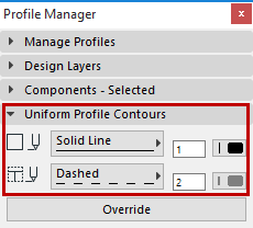
Cut lines: Choose a uniform line type and pen color for all of the cut lines (outer lines) of the profile element.
Separators: Choose a uniform line type and pen color for all of the separator lines (inner lines) of the profile element.
Override: Click this button to apply the Cut Lines and Separator settings to the respective lines in the Profile Editor window. These uniform settings will override all individual line settings.
Note: Lines that separate two fills having the same Building Material will be eliminated; the two fills will be merged into one.
Apply Custom Surface or Line to Profile Edge
By default, all sides of a Profile element use the surface defined in its Building Material.
However, you can apply a different surface or line type to any edge of any Profile component.
1.Select a profile component fill in the Profile Editor window.
2.Choose the Custom Edge Settings pet palette icon.
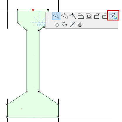
3.Edit the controls in the appearing Custom Edge Settings dialog box.
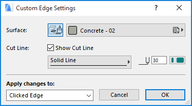
To switch off the contour line of the selected edge, uncheck Show Cut Line.
These custom edge settings will be applied to the edge from which you opened the Pet Palette (Clicked Edge), or to all edges. If needed, you can apply a different custom edge surface/contour line to each individual edge.
If you are using a custom line type or pen for any edge(s) of the profile, the Fill Selection Settings will indicate this with a custom icon: