For general information, see 3D Projections.
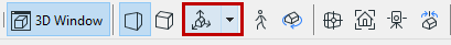
Use the View > 3D View Options > 3D Projection Settings command or the 3D Visualization toolbar’s button to open this dialog box.
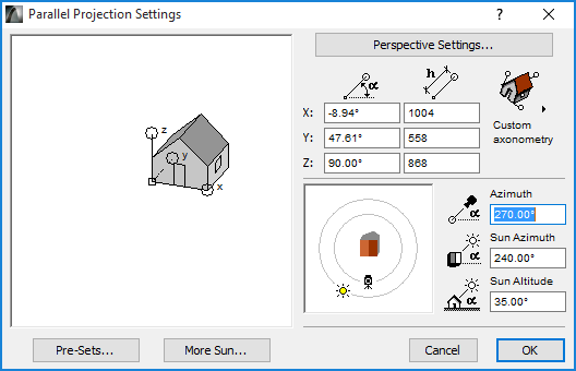
Use the controls in this dialog box to set up 3D views as parallel projections.
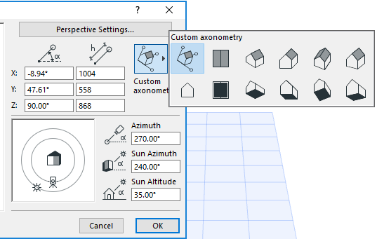
Click this pop-up button to select from 12 preset Projection Types, including predefined axonometrics, side, top and bottom views, and your own custom-defined axonometry:
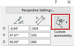
For each Projection type, the editable boxes show the defining angles and scaling ratios of the X, Y and Z coordinate axes.
Projection Preview: This preview window shows the position of the coordinate axes for the current projection type, with any additional settings you may have made. Click or drag to reposition the axes, or enter values for the angles and ratios of the three coordinate axes.
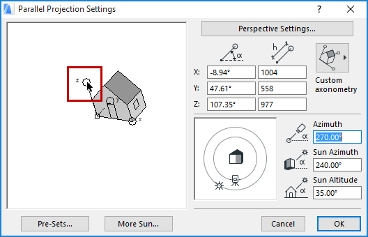
This dial shows Camera and Sun Azimuth with respect to the target. Simply click the Sun or Camera icon and drag it to the desired location. The effect of your changes is shown by the rotation of the house in the preview area and by the values in the edit boxes to the right of the control.
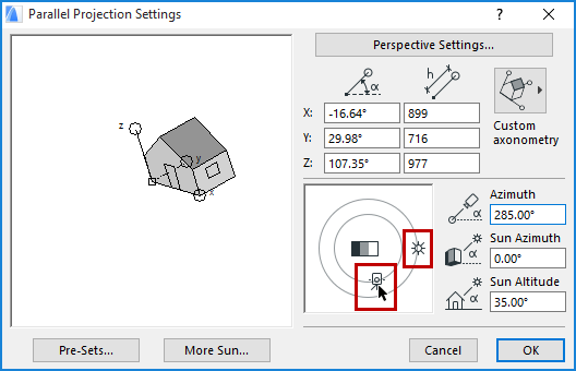
•To move the camera or the sun in 45 degree increments, click once near the desired direction on either of the gray circles.
•To move them in 5 degree increments, drag the camera or sun icon.
•To move to any in-between position, type the desired numeric value into the edit fields.
Another way to create a customized axonometry is to manipulate the house icon itself in the preview area:
•To rotate an axis about the origin, click on or near it and drag it to the desired orientation.
•To rescale and rotate an axis, click within the circle at its endpoint and drag it to the desired position. Use the Shift key to lock the angle while dragging. (If you only want to rescale, it is easier to enter a value in the edit box.)
The adjustments you make here are continuously reflected both by the values displayed in the edit boxes, and by the distortion of the house icon itself.
You can set the direction of your view and the position of the sun with the controls and edit boxes to the right of the preview area.
The Azimuth of the camera and the Sun Azimuth can be set either graphically or numerically, but the sun Altitude angle can only be set numerically:
•Azimuth: Enter a value here to specify Camera Azimuth to Target.
•Sun Azimuth: Enter a value here to specify Sun Azimuth used in shaded or rendered images.
•Sun Altitude: Enter a value here to specify Sun Altitude used in shaded or rendered images.
Just as for perspective projections, the distance of the sun from the target is considered to be infinite, and for parallel projections the viewpoint distance is infinite as well.
Hint: Unless you are an experienced ARCHICAD user, it is generally best to begin with a predefined projection from the palette, then rotate the view with the camera angle control, and finally make minor adjustments with the rescaling features.
Pre-Sets: Button: Opens a dialog where you can specify options for and insert frames in Fly-Through Paths.
For details, see Pre-Set Projections below.
More Sun Button: Opens a dialog to specify Sun settings.
For details, see Sun.
Perspective Settings: Click here to open Perspective Projection Settings, where you can define perspective views.
For details, see Perspective Projection Settings.
This dialog box lets you store and retrieve projection settings. You can also use this sequence of axonometric views for a future animation. Animations based on axonometric views are not fly-throughs in the same sense as perspectives, even though they are created with the same command. Using in-between frames, you will get an animated metamorphosis from one projection to the other.
•The Add Current Projection button places the current view on the list. The views on the list will be keyframes in the Fly-Through. You can also name each keyframe in the dialog box that appears after pushing this button.
•If no projection is selected, New will be added to the bottom of the list. If a projection is selected, the new projection will be inserted before the selected one.
•The Set to Current Projection button changes the highlighted keyframe in the list to the one you set prior to opening the Pre-Sets dialog box.
•The Delete button clears a keyframe from the list.
•Under Options for Fly-Through in the right section of the dialog box you can also set the number of in-between frames that ARCHICAD will create by interpolating between every parameter (e.g., axis scaling ratio, camera angle, etc.) of consecutive keyframes.
For more information, see Fly-Through.
•The Open and Closed radio buttons control whether the animation will loop continuously from the last defined keyframe back to the first keyframe during the Fly-Through.
•Wait frames: This number refers to the number of still frames (time units) during which the fly-through motion will remain frozen at the given camera before moving on to the next one.
Enter the number of still frames to be included in the Fly-Through Path.