
Curtain Wall Settings: System Page
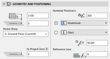
Curtain Wall Settings: System Page: Geometry and Positioning Panel
For the Curtain Wall’s default settings:
Nominal thickness: Enter the nominal thickness of the Curtain Wall. This is the distance from the Reference Surface to the theoretical opposite side of the Curtain Wall - as defined by you. The Nominal thickness value is used by elements connected to the Curtain Wall:
•adjoining zones will extend to the nominal thickness of the Curtain Wall
•connecting walls will also, by default, extend to the nominal thickness of the Curtain Wall.
See also Join Wall to Curtain Wall.
Home Story: Choose one of the following Home Story settings:
•Current: The Home Story will be the Current Story.
•Select Home Story: Choose a story to which to link the Curtain Wall. Click Select Story to bring up the full list of stories in the project.
The Curtain Wall’s reference line is physically linked to its Home Story. If you later modify the Home Story’s position (e.g. redefine the floor level), the Curtain Wall will change its position.
If you change an element’s elevation so that its reference line is moved to a different story, you have the option to make the Home Story change to match the element’s new location:
See Change Home Story by Elevation.
For more information, see Home Story.
Frame Building Material: Click to select a Building Material for the Frame.
Note: While a Curtain Wall Frame does have a Building Material, the Building Material’s intersection priority is ignored.
Panel Building Material: Click to select a Building Material for the Frame.
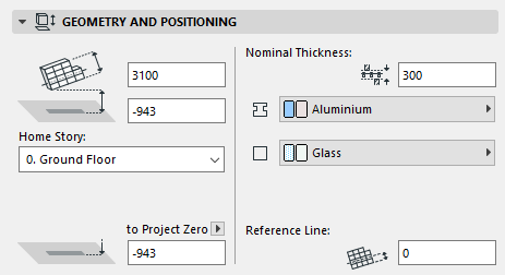
For the Curtain Wall’s Selection Settings:
The rest of the controls on this panel are only editable in Curtain Wall Selection Settings for a selected Curtain Wall. (To define these values when placing a new Curtain Wall, you will use the Place Curtain Wall dialog box that appears when you start drawing the Curtain Wall.)
For a Curtain Wall with a horizontal Reference Line:
•Relative Base Height
•Bottom Elevation [to Reference level]
•Reference Line Offset
•Slant Angle (not available for multi-segment Curtain Walls)
For a Curtain Wall with a non-horizontal Reference Line:
•Curtain Wall Height = Length of extrusion (measured in the plane of the Curtain Wall, in the direction of extrusion)
•Relative Base Height/Bottom Elevation to Reference level = Height of the Curtain Wall’s lowest point (Relative to Home Story, and to the reference level)
•Offset of Reference Line from lower edge (measured in the plane of the Curtain Wall, in the direction of extrusion
Curtain Wall Settings: System Page: Offset to Reference Surface Panel
Use these controls (the four editable fields) and consult the image to define
•the offsets between the Reference Surface and the Boundary, Mullion and Transom Frames
•the offset (Panel offset) between the Reference Surface and the Base Surface on which the panels are placed
The four editable offset values here are interrelated; changing one will change all the rest.
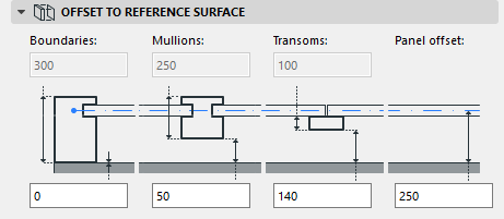
The frame depths of each of the three frame classes are defined on the Frame pages of Curtain Wall settings, and are not editable here.
See Curtain Wall Settings: Frame Pages (Boundary, Mullion, Transom).
Curtain Wall Settings: System Page: Floor Plan and Section Panel
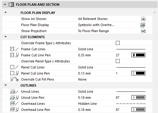
Use these controls to define the appearance of the Curtain Wall: its Floor Plan Display; its Cut Elements (appearance of cut frames and cut panels); and its Outlines.
Floor Plan Display
Show on Stories: Choose an option to define which stories will display the wall.
•All Relevant Stories: A multi-story Curtain Wall will be displayed and editable on all stories which it intersects. Multi-story Curtain Walls will be correctly joined with other elements on all stories where the multi-story Curtain Wall is present.
•Home Story Only: This Curtain Wall will be displayed on its Home Story only.
Floor Plan Display
Note: The Symbolic option for Floor Plan Display is recommended for regular, vertical Curtain Walls. For other geometries, the Projected options will work better.
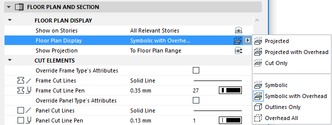
•Projected with Overhead: shows cut part of Curtain Wall’s 3D model (i.e., as cut at the level of the Floor Plan Cut Plane), plus the Curtain Wall’s overhead part (the part above the Floor Plan Cut Plane), and its uncut (downward) part.
•Projected: shows cut part of Curtain Wall’s 3D model, plus its uncut (downward) part.
•Cut Only: displays only the cut part, as cut by the Floor Plan Cut Plane.
Three additional abstract display options are available:
•Symbolic: Frame and Panel elements are depicted using symbolic display. Shows cut part of Curtain Wall’s 3D model (i.e., as cut at the level of the Floor Plan Cut Plane), plus the Curtain Wall’s uncut (downward) part.
In Symbolic mode, Accessories and Junctions are not shown at all on the Floor Plan.
In Symbolic mode, only the Frame centerlines are displayed.
•Symbolic with Overhead: Frame and Panel elements are depicted using symbolic display. Shows cut part of Curtain Wall’s 3D model (i.e., as cut at the level of the Floor Plan Cut Plane), plus the Curtain Wall’s overhead part (the part above the Floor Plan Cut Plane), and its uncut (downward) part.
In Symbolic with Overhead mode, Accessories and Junctions are not shown at all on the Floor Plan.
In Symbolic with Overhead mode, only the Frame centerlines are displayed.
•Outlines Only: the entire Curtain Wall’s outline plus Frame centerlines are shown using uncut attributes.
•Overhead All: the entire Curtain Wall’s outline plus Frame centerlines are shown using overhead attributes.
The Show Projection pop-up contains three options:
•Entire Element: The Curtain Wall will be displayed on all relevant stories.
•to Floor Plan Range: Choose to show the Curtain Wall on a range of stories (the current story, plus a given number of stories above and below it).
If you choose this option, then you can set the desired range (i.e. the number of stories on which to show this Curtain Wall in either direction) in Floor Plan Cut Plane Settings.
•to Absolute Display Limit: Set a fixed lower limit (by default, this is Project Zero), then show all parts of the Curtain Wall above this limit.
If you choose this option, go to Floor Plan Cut Plane Settings to set the Absolute Display Limit.
For details, see Floor Plan Cut Plane Settings Dialog Box.
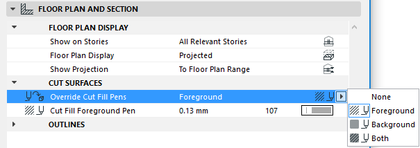
Cut Elements
Override Frame Type’s Attributes: If you are using a GDL-type frame: you can check this box to override the attributes defined in the GDL object, using the two controls below. (If your frame is not a GDL object, then the following line/pen settings will be used in any case.)
Frame Cut Lines: Click to select a Line Type for the Frame’s Cut Lines.
Frame Cut Line Pens: Click to select a Pen for the Frame’s Cut Lines.
Override Panel Type’s Attributes: If you are using a GDL-type panel: you can check this box to override the attributes defined in the GDL object, using the controls below. (If your frame is not a GDL object, then the following line/pen settings will be used in any case.)
Panel Cut Lines: Click to select a Line Type for the Panel’s Cut Lines.
Panel Cut Line Pens: Click to select a Pen for the Line Type used on the Panel’s Cut Surfaces.
Override Cut Fill Pens: If needed, override the fill foreground/background pens of this element (defined by default in the Building Material). To do this, choose Foreground, Background or Both from the Override Cut Fill Pens pop-up to access the respective controls.
Outlines
Uncut Lines: Click to select a Line Type for the Uncut Lines of the Curtain Wall.
Uncut Line Pens: Click to select a Pen for the Uncut Lines of the Curtain Wall.
Overhead Lines: Click to select a Line Type for the Overhead Lines of the Curtain Wall.
Overhead Line Pens: Click to select a Pen for the Overhead Lines of the Curtain Wall.
Curtain Wall Settings: System Page: Member Placement Panel
Use the controls on this panel to define how to place Junctions on your Curtain Wall, the direction of Mullion Frames, and where the Boundary Frame should be positioned relative to the grid.
Note: The Curtain Wall grid is defined as part of the Scheme, on the Scheme page of this dialog box.
Place Junctions: Click One by one to place Junctions individually using the Junction tool. (Individual Junctions can be placed in Edit mode only, after you have placed and selected a Curtain Wall.)
Click At all Gridpoints to place a Junction at all points of the grid when the Curtain Wall is created, or at all gridpoints of a selected Curtain Wall.
Junctions are placed automatically at all gridpoints if:
•You have chosen All Gridpoints, and
•A valid Junction object is defined on the Junction page of Curtain Wall Settings.
Boundary Frame position: The Boundary Frame (whose other parameters are set in the Boundary Frame page of this dialog box) are placed along the edge of the grid - that is, along the Curtain Wall boundary.
By default, the Boundary Frame is placed so that the frame’s centerline coincides with the grid line (Center on Grid).
To offset the Boundary Frame:
•Click Inside Grid to place the Boundary Frame so that it is inside the boundary grid line.
•Click Outside Grid to place the Boundary Frame so that it lines up against the outside of the boundary grid line.
This control lets you define which direction the Mullion Frame will run with reference to the Curtain Wall grid.
The Curtain Wall grid has a primary and a secondary gridline direction; you must associate the Mullion frames with one of these directions.
Primary Gridlines: The Mullion Frame will be the frame that coincides with the primary grid.
Secondary Gridlines: The Mullion Frame will be the frame that coincides with the secondary grid.
The Transom frames, then, will be associated with the other gridline direction.
The Boundary frame always runs along the Boundary polygons.
(The properties of these Frame classes - Boundary, Mullion Transom - are defined on the corresponding pages of Curtain Wall Settings.)
Important: The parameters of the Curtain Wall’s primary and secondary grid are defined by you on the Scheme page of this dialog box. There is no relation between the Curtain Wall grid and ARCHICAD’s grid system.
Relation to Zones: Click this field to define the relationship of the Curtain Wall to Zones. This field defines whether the new Curtain Wall is a Zone delimiter, an element to subtract from the Zone’s area or to be ignored when calculating Zones.
•Zone Boundary: This option means that a Curtain Wall located inside a zone will not be included in the zone area. In every case, including slanted Curtain Walls, the zone boundary is drawn at the base of the Curtain Wall. Multi-story elements in automatic display mode can serve as zone boundaries on any story on which they exist, not just their Home Story.
•Reduce Zone Area Only means that the 2D zone will encompass the Curtain Wall, but the Curtain Wall area will not be included in the zone area. (Zone Volume, however, will include the Curtain Wall.)
•Subtract from Zones means that when calculating the zone’s 3D volume, the volume will not include the volume of any Curtain Wall located inside the zone.
•No Effect On Zones means that the Curtain Wall has no effect on the zone; the zone area and volume will include the area covered by the Curtain Wall.
For more information, see Calculating Zone Area and Zone Volume. See also Relation to Zones.
Curtain Wall Settings: System Page: Categories and Properties Panel