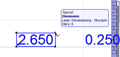
To open the Dimension Text Settings dialog box, you must first select the Dimension Text item (not the entire Dimension line).
Select Dimension Text
To select a Dimension text, do one of the following:
•Use the Quick Selection cursor
•Click on a corner of the text with the Checkmark with Arrow cursor
Note: To select a Fill Area text, make sure you have enabled Textbox handles at View > On-Screen View Options.
Open Dimension Text Settings
Select a dimension text (see above), then do one of the following:
•click the Text icon in the Info Box
•double-click the Dimension Tool icon in the Toolbox
•use the Ctrl+T shortcut
•click the Edit > Dimension Text Settings command. (This command is only available when a Dimension Text is selected.)
Change Position of Dimension Text Item
See Graphical Editing of Text Box and Pointer Line.
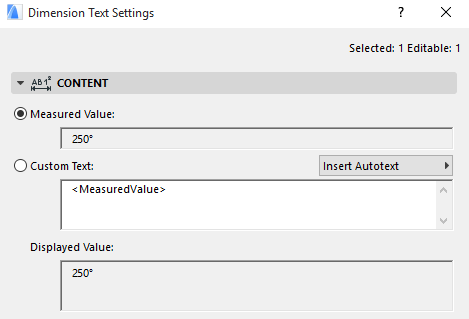
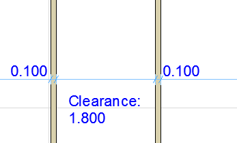
This field displays the measured value of the selected dimension.
The unit and accuracy of the dimension value can be set separately for each type of dimension value (e.g. length, angle, area) at Dimensions Preferences (Options > Project Preferences > Dimensions).
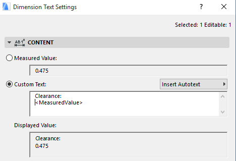
Choose this option if you want to add custom data to the dimension text. By default, the <MeasuredValue> Autotext item is displayed in the edit field as soon as you click the Custom Text radio button.
Note: For Level Dimensions, the <toPZValue> Autotext item is shown, representing “Project Zero” as the dimension origin.
In the Custom Text field, enter any custom text before and/or after the Autotext (or in place of it).
You can add multiple lines of custom text, separated by the Enter key.
Such line breaks are shown in the Info Box with the Paragraph sign.

Regardless of any additional custom text that you may have added, the Autotext remains associative - that is, if you edit the dimension line, the Measured Value will be adjusted accordingly.
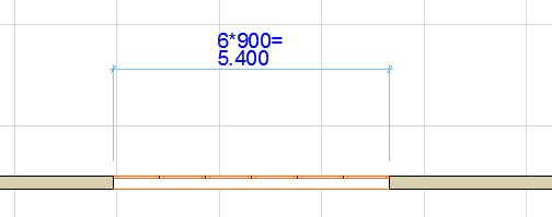
Insert Autotext as Dimension Text
From the pop-up field to the right, you can choose from additional Autotexts to add to the Dimension text field. The contents of this list depend on the type of dimension (e.g. Linear or Elevation dimension):
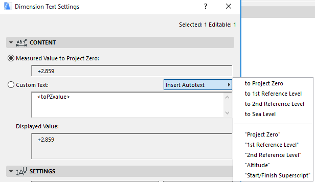
Autotext means that the Dimension text will display the current value of the chosen Autotext reference: for example, if you have defined a reference level called Sea Level, you can choose to Sea Level here as the Autotext, and Dimension Text will display the elevation dimension to that level.
If you choose a text in quotation marks (e.g. “1st Reference Level”), this text itself will be displayed, not its value.
Note: To define your project’s reference levels, use Options > Project Preferences > Reference Levels.
See Reference Levels Preferences.
Add Superscript to Dimension Text
Use the Start/Finish Superscript Autotext if you want the Custom text to include superscript text; click this option to insert a caret before the superscript text, and click it again (or insert a line break) to finish the superscript with a second caret.
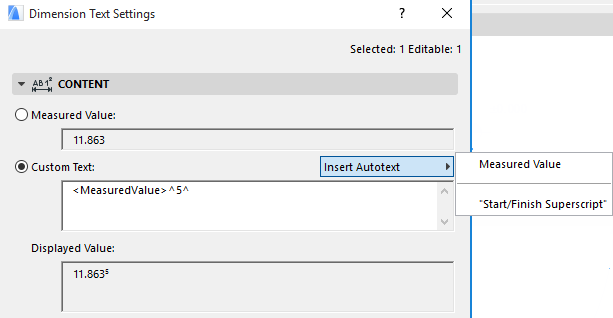
Note: If your dimension’s Measured Value already includes a superscript - because you are using Extra Accuracy defined in Options > Project Preferences > Dimensions - then add a space before inserting the Start Superscript caret. Otherwise, the caret itself will appear in the dimension text.
The Displayed Value field shows you what the dimension text will look like on screen.
Undo Changes to Dimension Text Content
To undo changes of all modified dimension text items at once, go to Document > Annotation and click the Revert All Custom Text to Measured Value command.
See Dimension Text Settings for information on editing style and font type of dimension text.
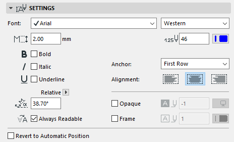
The Settings panel lets you set the font size, style, angle, and orientation of the selected dimension text.
Note: Favorites of the Text tool can be applied to the text-type items in Dimensions and Labels, and to Fill Text.
Font: Select a font for the Dimension Text.
Text Script: Click this pop-up field to select a font encoding for the Dimension Text.
Text Height: Enter a font size for the Dimension Text here.
Note: Fractional sizes are allowed, but may be rounded.
Text Format: If desired, check the Bold, Italic, or Underline boxes to format the dimension text accordingly.
Choose a pencolor and pen weight for the text.
Text Rotation Angle: Enter an angle for the text rotation, if any.
Use the pop-up to define how this angle value should be interpreted when the element is placed:
• Relative to Orientation (the angle will be measured relative to the Oriented View)
See Set Orientation.
• Absolute to Coordinate System (the angle will be measured from the (0,0) point of the project coordinates)
The Always Readable option (on by default) means that the program will automatically “flip” the text to make it legible on screen (as opposed to upside down) regardless of the view’s orientation. This automatic “flip” occurs if the text is at an angle between 90 and 270 degrees.
Anchor: Relevant for multi-line dimension texts that are placed at the dimension line. Choose to anchor either the First row or Last row of text to the dimension line.
Alignment: Choose either Left, Right, Center or Justify to align the text in the text box.
Opaque: Check this box to set a background color for your dimension text block and activate the pencolor selection settings at right: open the pop-up menu to choose a color. The pen of this Fill may also be set to 0 (Transparent) or -1 (Window Background). Henceforth your text editor will also have this background color.
Frame: Check this box if you want the dimension text block frame to be visible. Checking the box activates the pencolor selection settings at right: open the pop-up palette to choose a color for the frame.
Undo Changes to Dimension Text Position
To reset the position of a selected text item, check the Revert to Automatic Position box at the bottom of the dialog box.
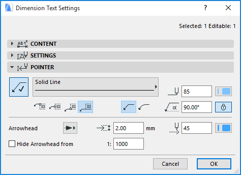
Use these settings for the optional pointer line of the Dimension Text.
Click the Pointer button to assign a pointer line and activate the rest of the settings on this panel:
•Define a Line type and Pencolor for the Pointer.
•Choose whether the pointer should have a straight or a curved pointer line.
•Enter the Pointer Starting Angle (the default is 90 degrees). Click the lock icon to prevent the angle from being modified graphically (e.g. by accident).
Note: The Lock Angle control affects the range of graphical editing. If it is ON, the Pointer Line’s starting angle remains fixed, limiting the edit possibilities.
•Choose where the pointer line should connect with the label: in the middle, at the top or at the bottom; or at the bottom with the text underlined.
•Choose a style and pencolor, and enter the size of the Arrowhead.
•Hide Arrowhead from: Check this box if you want to hide the pointer line arrowheads on views which exceed a certain scale (enter the desired scale in the field to the right).
To hide Arrowheads on all views, set the scale to 1:1.