Translators for Import (Detailed Settings)
An IFC Translator for Import defines the rules for handling model elements when importing an IFC-based file to ARCHICAD.
For an overview of this topic, see IFC Translators: Overview.
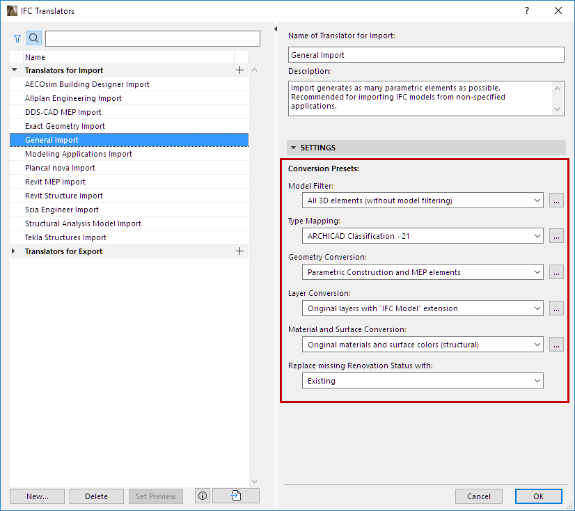
The IFC Translators dialog box (File > Interoperability > IFC > IFC Translators) allows you to view or modify Translator settings, or to create new Translators.
Select a Translator for Import from the list.
The selected Translator’s settings, divided into six Conversion Presets, are shown on the right side.

Working with Conversion Presets
For any category of Conversion Preset, click the dropdown list to view or select a different Preset. The Preset name gives you an idea of how it will affect the imported IFC model, if this Preset is used in a given IFC Translator for Import.
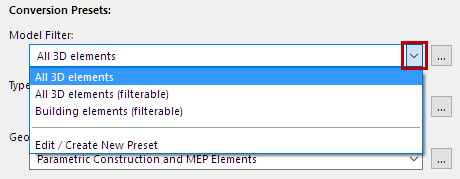
Choose a different preset from this list if needed.
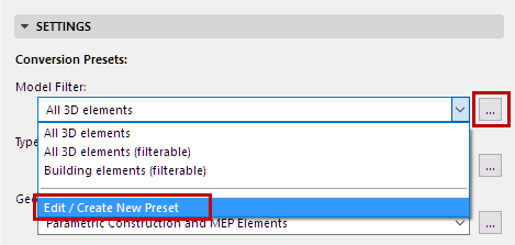
To adjust settings or create a new preset, select Edit/Create New Preset, or click the three buttons at the right of the Preset.
The Preset dialog opens (for example, the Geometry Conversion for IFC Import).
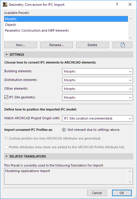
For each of the IFC Import Preset dialogs, view the following:
•Available Presets for this Conversion process (e.g. Geometry Conversion)
•Settings (this is where the import is defined in the greatest detail, for various data types, as defined for the currently selected preset at the top)
•Related Translators (all the currently defined IFC Translators for Import which use this Preset)
All Settings of each type of Conversion Preset (used by IFC Translators for Import) are detailed in the following sections.
Geometry Conversion for IFC Import
Layer Conversion for IFC Import
Material and Surface Conversion
Replace missing Renovation Status with:
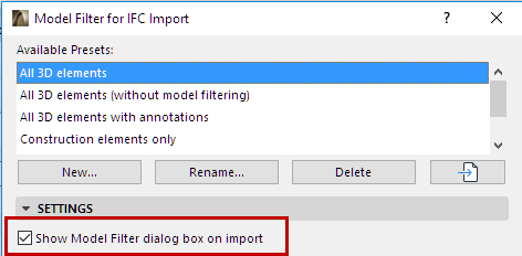
If this option is active, then - after you issue an Open or Merge IFC command - the Model Filter window will open.
This gives you the chance to overwrite, for the purposes of the current import process, the elements to be imported.
See Filter Model at Import (Secondary Filter).
Select 3D Elements to Import
Use the IFC Domain to filter according to the following criteria for IFC import:
◦“All” includes all elements from the model
◦“Structural” includes only the structural building elements (IfcBuildingElement)
◦“MEP” includes only the mechanical elements (IfcDistributionElement)
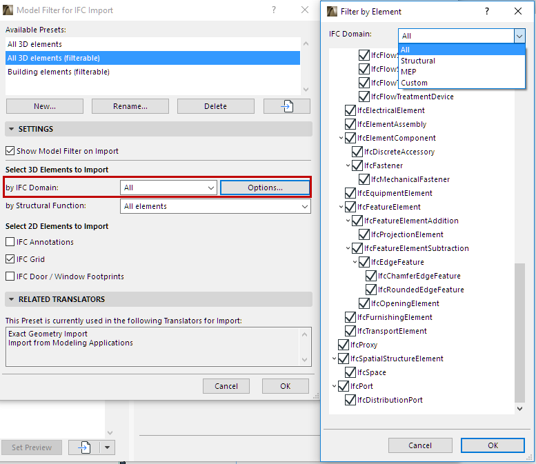
To see the exact composition of each Domain filter, click “Options”; modifying these options will create a “Custom” filter.
•By Structural function
Use this as an additional (element-level) filter for import purposes, which takes into account the elements’ “LoadBearing” IFC Property at import.
◦“Load-Bearing elements only” means that only those elements whose IFC Property “LoadBearing Element” has a “True” value will be imported from the IFC file to ARCHICAD.
Notes:
◦If no Structural Function classification has taken place in the ARCHICAD project, or if you have not finished the classifying process in ARCHICAD, then you should choose “All Elements” here: either of the other two settings (“Load-Bearing elements only” or “Non-Load-Bearing elements only”) can result an empty IFC file, or one that is missing elements you might need.
◦The default Options set here can be overwritten during the import process using the Model Filter options.
See Filter Model at Import (Secondary Filter).
◦IfcPile and IfcFooting entities are load-bearing structural elements by definition, although they have no "LoadBearing" property in the IFC 2x3 Schema. They are always handled as load-bearing elements at import.
•IFC Grid: During import, all IfcGrid elements of the IFC file will be imported and converted into grouped ARCHICAD Grid Elements.
•IFC Annotations: Check this to import all IfcAnnotation-type elements (including exploded dimension elements) of the IFC file into ARCHICAD. They will be converted into 2D elements (texts and lines).
•IFC Door/Window Footprints: During import, all generated doors and windows will be displayed in floor plan views with correct opening direction and sizes, based on their imported 2D symbols
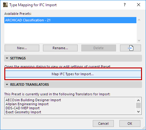
From this preset dialog, click Map IFC Types for Import to access the mapping definitions.
Use this chart to define how to classify IFC elements imported to ARCHICAD, based on their IFC Type.
At the top (“Target Classification System”), choose a Classification system in ARCHICAD whose definitions you want to use.
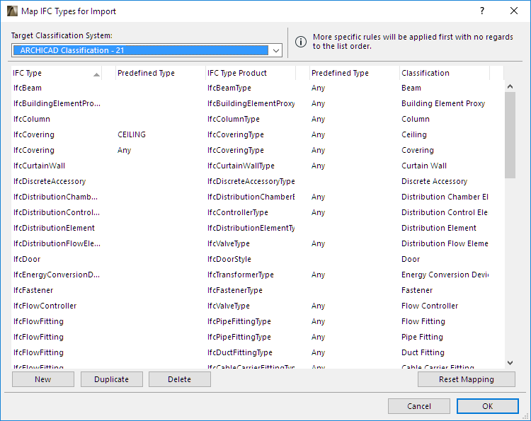
The IFC Type (far left column) is mapped to the Classification (far right column) as defined here. You can further narrow the mapping according to Predefined Types (if any) and IFC Type Products.
“Any” means that the mapping does not take the Type Product or Predefined Type definition into consideration when assigning the classification in ARCHICAD, even if the imported element has such a definition.
Watch the Video:
Element Classification: IFC Conversions and Properties
Geometry Conversion for IFC Import
Use this dialog box to define how to convert the geometry of IFC elements imported to ARCHICAD.
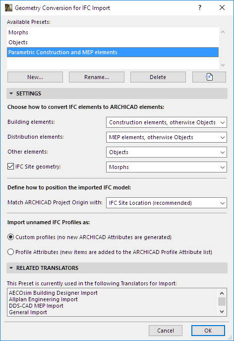
Building Elements
Convert to:
•Construction elements, otherwise Objects
•Construction elements, otherwise Morphs
With either of these options, IFC elements whose supertype is IfcBuilding (IfcWall, IfcColumn, IfcBeam, etc.) are imported as editable ARCHICAD elements (“Construction elements”: Wall, Column, Beam, etc.)
The advantage of converting the imported elements to AC tool-based construction elements is that they remain parametric, and ARCHICAD functions (such as automatic intersections) will apply to them.
Even if you choose the “Construction element” option, some elements cannot be imported in this form: such as non-extruded (BREP geometry) elements, or elements having no counterpart in ARCHICAD).
For such elements, you can choose to convert them as either an editable Morph or an Object (“otherwise Objects/otherwise Morphs”).
•Morphs
•Objects
◦Conversion of elements to Morphs or Objects guarantees perfect geometry import.
◦The resulting Morphs will be editable.
◦The resulting Objects will be Library Parts, whose subtype will match the IFC entity type: for example, an IfcColumn converted to an ARCHICAD Object will have the subtype “Column”.
Distribution elements
This option applies to imported elements whose domain is MEP (IfcDistributionElement).
These elements can be converted to one of three results:
•Morphs
•Objects
◦Conversion of elements to Morphs or Objects guarantees perfect geometry import.
◦The resulting Morphs will be editable.
◦The resulting Objects will be Library Parts, whose subtype will match the IFC entity type: for example, an IfcColumn converted to an ARCHICAD Object will have the subtype “Column”.
•MEP Elements: If GRAPHISOFT MEP Modeler Add-On has been installed, this option generates parametric MEP elements. Even if you choose this option, the MEP IFC model might not contain sufficient data to generate the parameters, in which case non-parametric MEP Equipment elements will be generated, or - in case of limited data - Objects will be generated.
Other elements
This option defines how to convert elements that are neither building elements nor distribution elements (such as furnishing and transportation elements).
•Morphs
•Objects
◦Conversion of elements to Morphs or Objects guarantees perfect geometry import.
◦The resulting Morphs will be editable.
◦The resulting Objects will be Library Parts, whose subtype will match the IFC entity type: for example, an IfcColumn converted to an ARCHICAD Object will have the subtype “Column”.
IFC Site geometry
Check this box if you want to include the geometry of the imported IfcSite.
Define whether the converted element should be an editable Morph or an Object. (IfcSite geometry cannot be converted to an ARCHICAD Mesh.)
Define how to position the imported IFC model
Match ARCHICAD Project Origin with:
•IFC Site Location (Recommended)
Import Unnamed IFC Profiles
Choose how to handle unnamed IFC profiles imported to ARCHICAD:
•Custom Profiles (this option does not create any new attributes in the ARCHICAD project)
•Profile Attributes (new Profile attributes are added to the ARCHICAD project)
Notes on Geometry Conversion:
•To optimize the management of shared geometry, ARCHICAD creates as few geometric elements (when generating Morphs) or as few Library Parts (when generating Objects) as possible.
•Objects can be placed in the project’s Embedded Library, or else saved to a given linked library (see IFC Local Preferences).
•Some IFC models may contain elements with special geometry which cannot be converted to Morphs, even if you choose the Morph conversion option. In this case, ARCHICAD will generate Objects, to achieve perfect geometry import.
•Imported IfcSpace elements will always be generated as ARCHICAD Zones, which will always retain the imported elements’ original geometry.
Layer Conversion for IFC Import
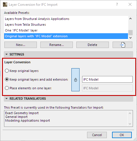
Define the method for placing the imported elements onto ARCHICAD layers.
•Keep original layers: ARCHICAD will create layers using the original layer names (IfcPresentationLayerAssignment) of the IFC model, and will place the imported elements onto these layers.
•Keep original layers and add extension: ARCHICAD will create layers using the original layer names of the IFC model, adding a custom extension (such as “Structural Model”) to each. (Enter the desired text in the input field). The advantage is that you will be able to sort the layers by extension in ARCHICAD’s Layer Settings dialog box.
•Place elements on one layer: Imported elements will be placed onto a newly created, single layer that you define (such as the “IFC Import” layer). (Enter the desired text in the input field.) Original layer names of the IFC model will be lost.
Notes on Layer Conversion:
•The import process automatically sets an intersection group number for all imported layers, and this number will be different from the current project layers' intersection group number. This difference ensures that the elements on the imported layers will not intersect with the existing project elements.
•If the elements have been converted to their counterpart ARCHICAD tool-based construction elements (that is, they have not been converted to Objects or Morphs; see Geometry Conversion for IFC Import above), then elements on identical layers might have their geometries modified due to automatic intersections. If you want to avoid this, set the intersection group number to 0.
•If layers of the same name already exist in ARCHICAD, no new layers are created; the imported elements are placed onto the corresponding, existing ARCHICAD layers.
•If the import involves elements whose geometries are generated by Solid Element Operations, then the operator elements are placed on the “IFC Openings” layer, which is hidden. If you move any of the target elements, make sure that the operator elements’ layer is shown, and move the target and operator elements together: do this to avoid modifying the original geometry of the imported elements.
Material and Surface Conversion
Choose how to assign ARCHICAD Building Materials to imported IFC model elements.
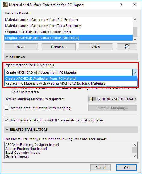
There are two import methods:
Method 1: Replace IFC Materials with existing ARCHICAD Building Materials
With this method, a single ARCHICAD Building Material is assigned to all imported IFC elements. Choose this default Building Material from the pop-up below. No new Building Materials are generated.
If needed, you can override this default definition by using Material Mapping: see Override default Material with mapping, below.
Method 2: Create ARCHICAD Attributes from IFC Materials
For each IFC Material, a new ARCHICAD Building Material will be created: the default Building material chosen below will be duplicated.
The new Building material:
•is named using the IFC Material’s Name parameter
•is assigned a color corresponding to the IFC Material Color parameter
Override default Material with mapping
Check this box to map individual materials manually, instead of using the default Building Material assigned from the pop-up.
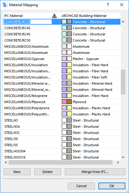
Click Merge from IFC to browse for the IFC model and import its IFC Material names to the Mapping dialog box.
Alternatively, click New to add an IFC Material name manually.
Note:
◦Some of the default IFC Translators for Import include predefined mapping rules, whose settings you are free to expand or edit. It is recommended to duplicate the default translator before modifying it.
◦You cannot import or export these mapping tables as separate files (e.g. xml); you must import/export them together with entire translator file itself.
Override Material colors with IFC element geometry surfaces
IFC elements in IFC models can have two colors: a material color and an additional color for the surface geometry color.
If you check this Override Material colors box, ARCHICAD will create Surface attributes using the color assigned to the IFC element’s surface geometry.
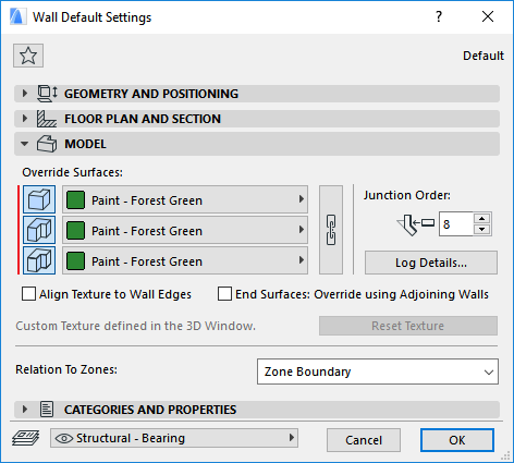
To check and modify the resulting surface overrides in ARCHICAD, view the Model panel of the respective Element Settings dialog box.
Replace missing Renovation Status with:
This preset does not have a separate dialog box.
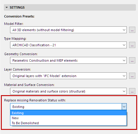
Choose a Renovation Status in ARCHICAD (New, Existing or Demolished) for imported elements that do not have an assigned renovation status.
Notes:
◦Nearly every model exchange scenario will lack automatic mapping of renovation status. The reason is that the IFC 2x3 standard has no standard format for renovation status, and so the various applications will export this data only as custom IFC properties.
◦In model exchange with Revit, the ARCHICAD “Renovation Status” item is mapped to Revit’s “Phasing” item, provided that the IFC export and import on the Revit side is carried out using the GRAPHISOFT ARCHICAD Connection Add-In
(http://www.graphisoft.com/support/archicad/downloads/interoperability.)