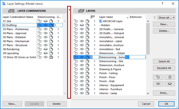
Use this dialog box to create, edit, and manage layers.
For more information, see Layers and Layer Combinations.
To display Layer Settings, use one of the following:
•The Layer Settings icon in the Quick Options bar
•Options > Element Attributes > Layer Settings
•Document > Layers > Layer Settings (shortcut: Ctrl+L)
•Click the relevant button of the Arrange Elements toolbar:

The left panel lists existing Layer Combinations. The right side lists all the layers defined in the project. Use the splitter bar that separates the two sides to display as much text as you need.

Double-click anywhere on this splitter bar to open/close the Layer Combinations panel (or click the black arrow at the top of the splitter bar.)
Multiple selection is possible. All the commands detailed below act on selected Layers.
To quickly change the layer status of several layers at once, use the shortcuts in the Quick Layers palette.
See Quick Layers.
Editing Layer Status
Select a Layer on the right side of the dialog box to edit it.
Note: The first item on the list, the ARCHICAD Layer, cannot be deleted, hidden or locked. This layer collects all those elements that may have lost their layer definitions.
Click on the icons of the selected layer to change its status.
Lock/Unlock
•The open or closed lock icons indicate whether a Layer has been locked to prevent its contents from accidental modification. If a Layer is locked, the elements on it cannot be edited or deleted and no new elements can be placed on it.
Show/Hide
•Use the open or closed eye icons to show or hide a selected layer. Elements on a hidden layer will be hidden.
Note: To show all Layers while working in your project, use the Document > Layers > Show All Layers command or the relevant button of the Arrange Elements toolbar.
3D View Display
•The solid model or wireframe icons indicate that the elements placed on that layer are fully visible in 3D views or with their contours only, independently of the current 3D mode set in the Image menu. This can be useful, for example, for storing the operator elements of Solid Operations on wireframe layers and target elements on solid layers.
•Set an intersection group number in the first edit box.

Note: Layer Intersection numbers have nothing to do with element priorities; they serve merely as tags or labels (e.g. 0 or 1) for grouping elements.
Note: Two elements that are both set to intersection group 0 will NOT intersect.
See Use Layers to Prevent Intersections.
•Add an extension to the layer’s name. This can act as an additional sorting control if you have many layers.
Tip: Layer extensions can be used effectively for project phasing and option management as well.
Sort Layers
You can sort Layers in the list alphabetically either by Name or Extension, or sort them by status or intersection group number, by clicking any of the column headers.
Use the pop-up items by the funnel icon to limit the display of layers in the list:
The funnel icon varies depending on whether you have applied a filter.

•Show all layers: All layers in the project are shown. Layers of XREF items are listed separately at the bottom of the list.
For more information, see Attributes of XREF Files.

•Hide XREF layers: If you have XREFs in your project, and if you choose this option, then the XREF layers will not appear in Layer Settings.
•Filter by extension: This option is available if the selected layer has an extension. Only layers having this extension will appear in Layer Settings.
Select All/Deselect All: Use these buttons to select and deselect all layers, respectively.
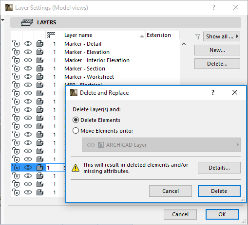
Delete: Click to remove the selected layer. This is not undoable. If you proceed with deleting the layer, all the elements on it will be cleared. In addition, the deleted layer attribute will be missing from your project. ARCHICAD displays a warning and details on the missing elements/attributes prior to actually deleting the layers.
When deleting a layer, you have the option to replace it with a different layer. In this case, the elements from the deleted layer are placed onto the layer you specify.

Note: In Teamwork, only elements reserved by you will be placed on the replacement layer. All other elements from the deleted layer will have a “Missing” layer.
See also Reserve and Delete Layers (Teamwork).
New: Click this button to create a new layer and give it a unique name.
See Layer Combinations.
Print Layer List
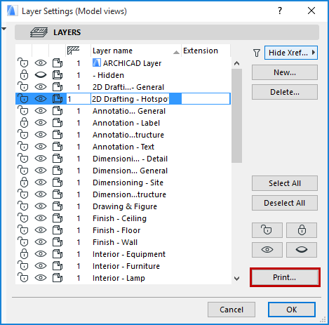
The Print... button at the bottom right of the Layer Settings Dialog Box creates a text-format list, in a PDF file, of the layers in your project.

This is a simple list, organized by Layer Combination. Within each Layer Combination, the layers are listed in order of their Attribute numbers. (These attribute numbers are not visible in Layer Settings; they are seen in the Attribute Manager opened from Options > Attributes > Attribute Manager.)