
Save Custom-Shape Doors or Windows
Use this method to create a door or window having a custom shape.
For rectangular shapes, see Save Rectangular Doors and Windows from 3D Model Elements.
In this process, you must create
1.a custom shape that will serve as the door/window itself, and
2.another shape that will be serve as the hole or niche into which the custom door/window will be placed.
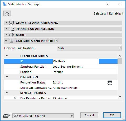
The shape of the hole is defined by a freely drawn slab or a roof, which is then assigned an ID of Wallhole or Wallniche. Slabs and roofs bearing these IDs will be displayed as a hole or a niche in the wall. (Wallhole and Wallniche are GDL commands used to create holes or niches in walls.)
To save a custom-shape door or window, do the following:
1.Create the 3D model of your custom shape window or door on the floor plan as described at the previous section.
See Save Rectangular Doors and Windows from 3D Model Elements.


2.Using the Slab or Roof tool, create another element whose contour matches the outer contour of the desired wall hole or wall niche.

3.Select this Slab or Roof and open its settings dialog.
4.Go to the Classification and Properties panel and change the ID field to Wallhole if you want to make a hole and Wallniche if you want to make a niche in the wall.
Note: The Wallhole-type element - regardless of its thickness - will always cut through the wall into which it is placed. The Wallniche-type element, however, will cut into the Wall to an extent that depends on its thickness, as set in Slab/Roof Settings. If you are making a Wallniche, be sure to set the element’s thickness to the desired value.

5.Move the Wallhole (Wallniche) element onto your custom window elements.
6.Select all the elements that will compose your custom-shaped door/window: that is, the door/window element(s) plus the hole/niche element.
7.Save the selection using the File > Libraries and Objects > Save Selection as command, and choose Window or Door.
8.You are prompted to specify which plane of the model represents the host wall plane (elevation plane), into which the new Door/Window will be rotated: either the current editing plane or the horizontal plane. (This is significant if, for example, you are saving an edited Morph element which was originally a door, and which is therefore not lying in the horizontal plane of your model.)

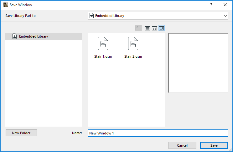
9.In the Save Door (or Save Window) dialog which appears, enter a name and choose the desired folder location for the new opening:
–to the Embedded Library (default choice. It is recommended to save customized, project-specific objects to your Embedded Library.)
–to a BIMcloud library that has been added to the project
–browse for a linked library
Click New Folder to create a new folder within the selected library folder.

10.Click Save.
11.The Change Object’s Basic Settings dialog box appears. Here, you can define the new library part’s default Surfaces, Fills and Pens.
Note: You can further fine-tune these attributes in Object Settings after you place the library part.
Also, to add information to your new library part (for example, keywords to make it easy to search for in Object Settings or BIM Components), click Change Details at bottom left.

12.Click OK.
13.Place the newly created Window/Door with the Window or the Door tool. Note that the created object is stretchable, but will be distorted after stretching since it was not scripted parametrically.
You can combine multiple slabs or roofs to create complex holes or niches. Since you can define inclination angle for the roofs, you can even cut non-perpendicular holes in walls.
For information on editing the resulting GDL library part, see Editing Custom Library Parts and Components.