Related Topics
Offset Modifiers: Tips and Tricks
Create Offset Modifiers to allow a placed Profiled element instance to be customized and modified locally.
A Profile can include multiple Offset Modifiers, and one Offset Modifier can include one or multiple dimensions (of the same length). Also, a single dimension can control multiple edges.
The following examples illustrate these features.
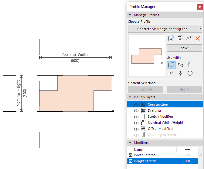
In this example, create a profile called Concrete Slab Edge Footing. You will add a modifier called “Base Width” to certain edges of this profile: after you place the element, you can graphically modify the Base Width edge.
1.In Profile Editor, draw the cross-section using the Fill Tool.
The Nominal Height and Nominal Width is shown. (The Nominal Width/Height display is turned on in the Design Layers panel.)
The Stretch Modifiers are also shown. (The Stretch Modifiers display is turned on in the Design Layers panel.) By default, the Stretch Modifiers coincide with the Nominal Height/Width dimensions.

Now, create an Offset Modifier called Base Width on particular profile edges.
2.In the Modifiers panel, click New Modifier.
3.In the New Profile Modifier dialog, give it a name: Base Width.
Or choose an existing name from the popup list, if this parameter has already been defined in another Profile in the same project.
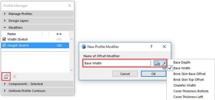
The newly created modifier appears in the Modifiers list. The initial warning triangle indicates that this modifier has no definition yet.

4.In the Profile Editor window, you are in dimension input mode. (If you are not in dimension input mode, click the Add Offset Dimension button in the Modifier panel as shown here.)

You have several options for defining the Dimension and anchoring it:
•Edge with Node Anchor
•Two Edges to Two Nodes (Anchored by Automatic End Nodes)
•Node and Node (with Neighboring Edge)
During input, available edges that can be offset are shown in black; when hovering, they will be shown with blue highlight.
Edge with Static Node Anchor
1.Click the edge to be offset.
2.Now drag the cursor: the modifier’s parameter name appears, and you are dragging its dimension line.
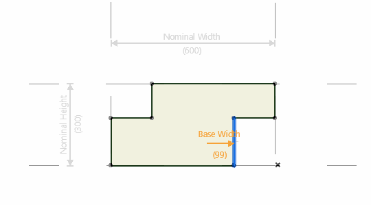
3.Click a Fill node (this is the anchor), then drag the resulting dimension line and click again to place it.
The result: You created an edge offset parameter that can be offset in the given direction, anchored from the clicked node.
The dimension end is a circle, indicating that its anchor is a node (rather than a static point).
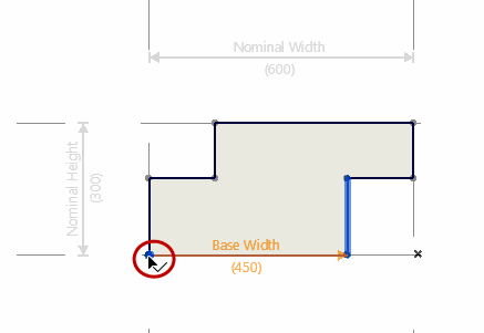
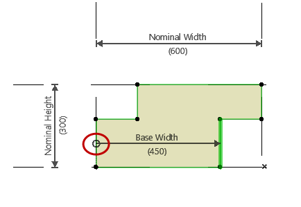
Modifier: Offset Single Edge, Anchored to Fill Node
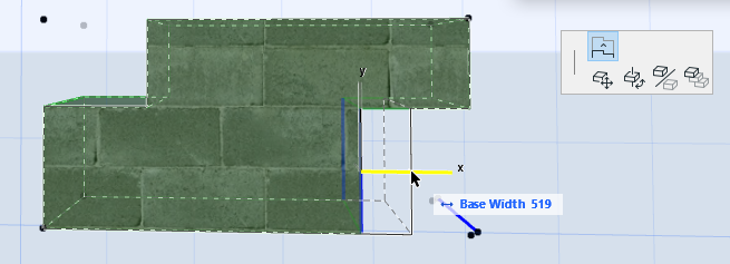
The anchor is associated to the Fill node, so if the profile’s Fill geometry changes, the anchor point (and thereby the modifier) will follow these changes.
Edge with Static Anchor
Alternatively, click anywhere in the Profile Editor to create a static point anchor (here, to the profile origin).
Then drag the resulting dimension line and click again to place it.
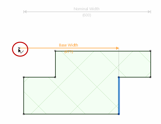
The dimension end is a square, indicating that its anchor is a static point (rather than a node).
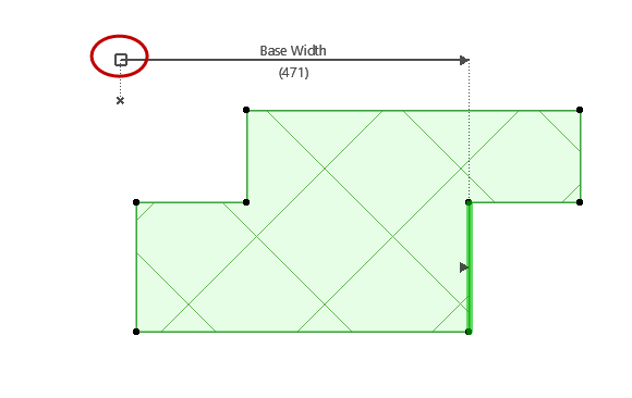
Two Edges to Two Nodes
Click the edge to be offset, then click a second edge. As you move the cursor, the dimension automatically finds the nearest end nodes to anchor to.
Then drag the resulting dimension line and click again to place it.
The result: You created an offset parameter with two edges. Modifying this parameter modifies both edges.
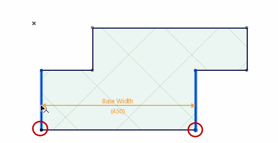

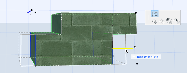
Modifier Offsets Two Opposite Edges
The two clicked edges do not have to be parallel.
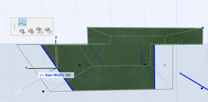
Node and Node with Neighboring Edge
Use this method to create a Modifier whose anchoring Dimension is not necessarily perpendicular to the offset edge.
Click two nodes representing the Dimension.
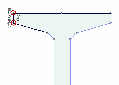
Then click the edge to be offset. The edge need not be perpendicular to the Dimension, but it must be adjacent to one of the clicked nodes.

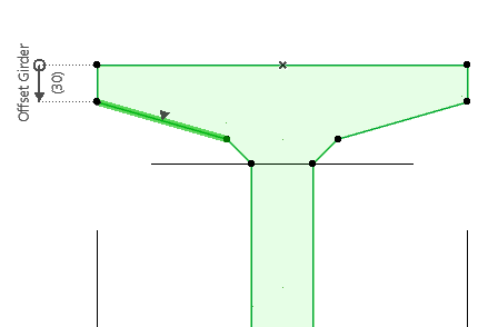
The result: The edge is offset perpendicularly, but is measured from the Dimension you specified.
