Beams and Columns are represented in the Structural Analytical Model as 1D Members. They have two nodes (start and end node) and one axis line connecting the nodes.
The 1D Member is generated by default at the center of gravity of the element’s core (or core component).

Customize 1D Member color at Structural Analytical Model Representation (Preferences).
The analytical Member does not extend outside of the physical body unless it has been adjusted.
Which Columns and Beams are 1D Members of the Structural Analytical Model?
Columns and Beams will generate a 1D Member in the Structural Analytical Model if they meet these conditions:
•Load-bearing
•Contains a core
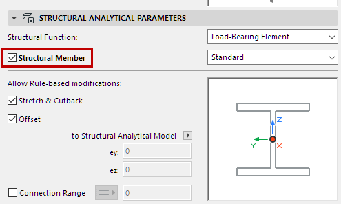
•“Structural Member” checkbox is activated in Element Settings
•Geometry is supported (see table below)
|
Beam-Column Geometry |
Member of Structural Analytical Model? |
|
Basic Element (Rectangular, Circular) |
YES |
|
Complex Profile - Includes a Core |
YES |
|
Complex Profile - No Core |
NO |
|
Multi-Segment and/or Tapered |
YES, based on user-defined Replacement Profile |
Use the Structural Analytical Parameters panel of Column or Beam settings.

Structural Function - Enable Load-Bearing
Set the Structural Function to Load-Bearing.
This is the same control, with the same value, as in the Structural Function control found in the Classification and Properties panel.

Structural Member - Enable for Structural Analytical Model
This box is checked by default: include this element in the Structural Analytical Model as a 1D Member.
Uncheck if the element should NOT be included in the Structural Analytical Model.

Notes:
–Available only if Structural Function is set to Load-Bearing.
–If the element is a composite or Complex Profile, it must include at least one Core skin/component in order to be part of the Structural Analytical Model.
1D Member - Define Structural Behavior
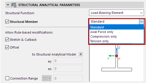
This Structural Behavior setting defines the Member’s behavior in a Finite Element Method (FEM)-based structural analysis program: specifically, which types of forces this element is designed to bear.

Choose an option to define the Member’s structural behavior:
•Standard (default) - The element can transfer all forces, such as axial and shear forces.
•Axial force only
•Compression only
•Tension only
The available definitions are fixed and cannot be customized.
The Structural Behavior setting has no effect on the Physical Model.
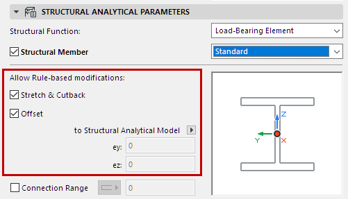
Allow Rule-based modifications - 1D Member
Activate these checkboxes to apply the respective Adjustment Rules that are defined in the Structural Analytical Model Generation Rules dialog box.
By default, the Stretch & Cutback and Offset boxes are checked: the Stretch, Cutback and Offset adjustments defined in the Generation Rules dialog affect this 1D Member element.

If an Adjustment Rule uses the “Snap” Adjuster, it will be applied to this element only if both checkboxes are checked.
See Structural Analytical Model Generation Rules.
To exempt this 1D Member from automatic adjustment rules, uncheck the box(es). The respective Adjustment Rules are not applied to this element.
If needed, you can set a custom offset for this element (see below).
Custom Offset
If the Offset box is unchecked:
Redefine this element’s eccentricity, either graphically or by entering a value.
See Eccentricity.
Connection Range
For Beams and Columns: This option virtually extends the 1D Member’s core length along its axis.
The purpose of virtually extending the core is to enable the Beam or Column to achieve a core connection with other elements, if such a core connection does not exist. As a result of this virtual extension, Adjustment Rules (which require core connections) can go into effect.
For details, see Connection Range (Extend Core to Enable Connection).
Translation and Rotation
See End/Edge Releases.