Save Options (DXF/DWG Translation Setup)
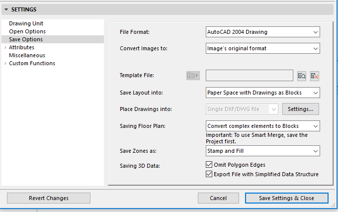
These are options in the DXF/DWG Translation Setup dialog box.
See DXF/DWG Translation Setup.
For additional save options, see also Custom Functions (DXF/DWG Translation Setup).

File Format
Define which version of AutoCAD you are saving your files to. The Smart Merge feature is available in all.
Convert Images to
Choose a format from the drop-down list for images saved to AutoCAD.
As a default, Image’s original format is selected; in this case, no conversion takes place.
Force output in AutoCAD picture formats: If this box is checked, the list of available image formats will show only those which the selected version of AutoCAD can read. The rest of the choices are disabled.
Note: If you have also selected Image’s original format, the picture will retain its original format only if it is recognized by AutoCAD; unrecognized file formats will be converted as TIFF.
Template File
Some settings in AutoCAD cannot be matched to anything in ARCHICAD, and vice-versa. For example, in ARCHICAD, layers do not have color and line type; in AutoCAD they do. The solution for the conversion of these settings is to choose a Template. The Template File is a DXF/DWG file where these conversions and changes are already done. If you choose a Template File with DXF/DWG export, elements going to the layer defined in the template file will have their layer’s color and line type set to the same values as in the Template file. This happens without the user even opening the resulting DXF/DWG file. The template file supplies the layer names defined in the file, so you don’t have to type them in, making it easier to create the layer conversion table.
Next to an edit field, the Browse button opens a file dialog from which to select a Template File.
Note: These Template Files may come from consultants. After you saved a DXF/DWG file for a consultant, he opens it and makes changes to it (e.g. to layers, pens etc.). Then he saves this file and sends it back to you. You will now have a Template File which you can use the next time you save DXF/DWG data for this consultant.
Browse for and select the template file, whose path is now displayed. From the pop-up icon at the left, choose to store this file location information either as an Absolute path or Relative path.
To delete the Template file, click the “Clear Template File” button to the right of the file path field.
Save Layout Into
Controls how and into what Space of a DXF/DWG file the content of the Layout is saved.
Paper Space with Drawings as Blocks: All elements drawn on the Layout, plus all drawing data will be saved into the Paper Space of the resulting AutoCAD drawing. All Drawings placed on the Layout will be converted into AutoCAD Blocks, and these will be clipped so only those portions of the Blocks will be visible in the AutoCAD Paper Space that were visible on the Layout in ARCHICAD. The purpose is perfect reproduction of what you saw on the Layout. With this option the Model Space of the resulting AutoCAD drawing will be completely empty.
Note: If you have placed ARCHICAD Floor Plans onto Layouts as Drawings, then the Library Parts, Zones and Doors/Windows from those Floor Plans can be converted into intelligent AutoCAD Blocks only if those Drawings have the status of “OK” in the Drawing Manager (in other words, if they are up to date).
See Managing and Updating Placed Drawings.
Model Space: All elements drawn on the Layout, plus all drawing data will be saved into the Model Space of the resulting AutoCAD drawing. All Drawings placed on the Layout will be converted into AutoCAD Blocks, and these will be clipped so only those portions of the Blocks will be visible in the AutoCAD Model Space that were visible on the Layout in ARCHICAD. The purpose is perfect reproduction of what you saw on the Layout. With this option a default Paper Space will be created in the resulting AutoCAD drawing, which will be empty.
-For Drawings whose source is internal to the project and whose Drawing status is up-to-date: their elements will be placed on identical layers in AutoCAD, subject to any layer-conversion preference in the DXF/DWG Translation Setup.
-For Drawings whose source is internal to the project, but whose Drawing status is not up-to-date (i.e. it is a manual-update drawing detached from the model): their elements will be placed on separate AutoCAD layers whose name is combined out of the Drawing’s name and ID.
-If the Drawings originated in external projects: their elements will be placed on a default layer in AutoCAD named “Drawings and Figures”.
•Paper Space with Cropped View’s content: Drawing elements manually drawn on the Layout will be saved into the Paper Space of the resulting AutoCAD drawing. The image of the Layout will be reconstructed in the Paper Space of the AutoCAD drawing. Drawings placed on the Layout will first become cropped by their placement polygon on the Layout (meaning only those elements and part of elements inside of the cropped area will be exported), and then saved in DXF/DWG format.
•Paper Space with Full View’s content: Drawing elements drawn on the Layout will be saved into the Paper Space of the resulting AutoCAD drawing. The image of the Layout will be reconstructed in the Paper Space of the AutoCAD drawing. Drawings placed on the Layout will be saved in their entirety in DXF/DWG format.
If you have chosen to save Layouts to Paper Space, the Place Drawings into field is enabled, where you can choose how placed Drawings should be saved:
•Single DXF/DWG file: All drawings (either cropped or in Full – depending on the value of the Save Layout into field) are saved into a single DXF/DWG file. They will be placed side by side in the Model Space of the file, and View Ports will be created in the Paper Space of this resulting AutoCAD drawing so in Paper Space they will look like the Layout in ARCHICAD.
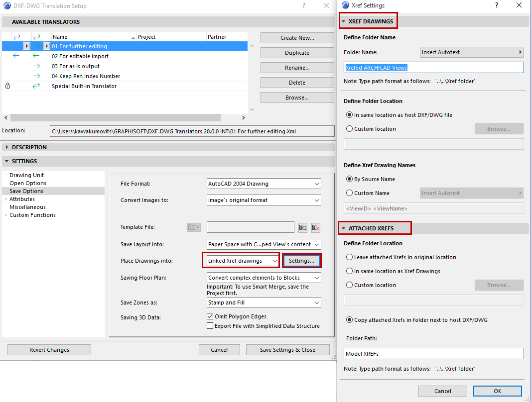
•Linked XREF drawings: A DXF/DWG file will be saved. In this file there will be placement references to XREF files. All files will be saved in other separate DXF/DWG files and these files will be placed in the first DXF/DWG file as XREFs. They will be placed side by side in the Model Space of the first file, and View Ports will be created in the Paper Space of this resulting AutoCAD drawing, so in Paper Space they will look like the Layout in ARCHICAD.
To the right, click Settings to open the Xref Settings dialog box.

Xref Drawings: The settings on this panel affect the name/location of Xref drawings created in ARCHICAD.
Define the folder path, folder location and drawing names of saved Xref drawings. Note that the folder path field can use Autotext.
Attached Xrefs: The settings on this panel affect the name/location of external Xrefs attached to the project.
Click OK to close this Dialog.
The following options are available only when saving Floor Plans:
•Convert ARCHICAD Elements to Blocks: Convert elements to blocks that are recognized by AutoCAD, so you do not have to explode them. (The resulting blocks consist of multiple 2D primitives.)
•Convert only Objects to Blocks: With this option, you will convert only GDL Objects to blocks. All other elements will be exported as drawing primitives.
•Explode ARCHICAD Elements: All elements are exploded into separate 2D primitives. Use this if you are exporting DXF files from ARCHICAD to a program which cannot process blocks.
•Prepare File for Smart Merge: Use this if you plan to merge a DXF/DWG file as part of a round-trip workflow. The conversion of elements takes place based on a customizable config file.
Important: To use Smart Merge, save the Project first.
For more information on Smart Merge, see Round-Trip Conversion (Smart Merge).
The Save Zones as option allows you to save Zones two ways: Stamp only, or Stamp and Fill.
The following options are available only when saving 3D Data:
•Omit Polygon Edges: The color of polygon edges in the 3D window of ARCHICAD is usually different from the color of surfaces. If you want to reproduce this look in AutoCAD, leave this checkbox empty. If you check the checkbox, the lines representing the edges won‘t get exported.
•Export File with Simplified Data Structure: The effect of this option is similar to the “Explode Complex ARCHICAD Elements” option – all the data goes into the entity section, instead of blocks.