Floor Plan Cut Plane (Global Setting)
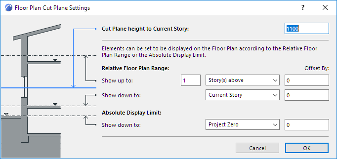
3D construction elements on the Floor Plan (Walls, Curtain Walls, Columns, Beams and Roofs) are displayed as if they were cut horizontally along a theoretical plane; this is the Floor Plan Cut Plane.
The default height of the Cut Plane, measured from the base of the current story, depends on local architectural conventions, but you can set any Floor Plan Cut Plane for the current window using the Floor Plan Cut Plane dialog box.
To set the Cut Plane, go to Document > Floor Plan Cut Plane
See also Floor Plan Cut Plane Settings Dialog Box.

Note: The Cut Plane does not affect the display of Mesh, Slab or Object elements. However, GDL Objects can be programmed to display themselves according to the Floor Plan Cut Plane Settings.
Enter a value for “Cut Plane Height to Current Story.”
If you wish to display all construction elements in their entirety, on all stories (the default settings for construction elements), the rest of the settings in the Floor Plan Cut Plane dialog box are not relevant.
The Relative Floor Plan Range and Absolute Display Limit - the other Floor Plan Cut Plane Settings - are only relevant if any of your construction elements are defined as having a limited projection.
The Floor Plan Cut Plane settings are global; the current settings apply to all the stories of the project. Once you set the global Floor Plan Cut Plane, you can further fine-tune the Floor Plan display of individual construction elements (Walls, Columns, Beams and Roofs only) in their element Settings dialog boxes.
For more information, see Element Display in Floor Plan and Section.
Set Separate Floor Plan Cut Planes in Different Views
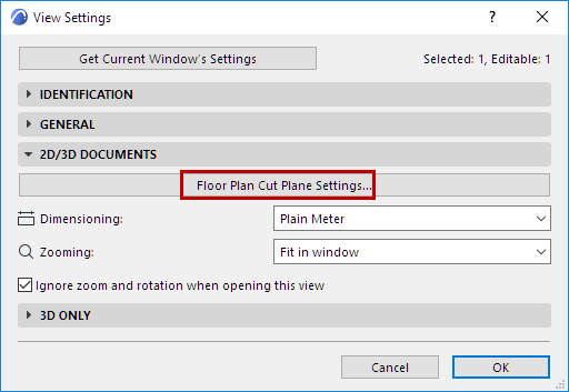
For every view, you can define a unique Floor Plan Cut Plane, if required, using the Floor Plan Cut Plane controls accessible from View Settings.
