Use this function to identify collisions among 3D elements in the model. A collision occurs when two or more elements physically intersect.
Collision Detection works by checking for collisions between any two groups of elements. The groups are defined by criteria chosen by you.
For example, you might run Collision Detection:
•Between construction and MEP elements. (MEP elements can come from hotlinked or merged external MEP IFC files, or else modeled inside Archicad.)
•Between concrete and steel construction elements
•Between elements classified as different product/element types (by Uniclass, OmniClass, UniFormat or any other classification system)
•To check the headroom clearance for escape routes or access for the disabled
Collision Detection is available from the Floor Plan and 3D windows only.
Access from:
•Design > Model Check > Collision Detection
•or click the Collision Detection icon from the Model Check Report
Example: Collision Detection with Volume/Surface Tolerances
Example: Headroom Collision Check
Exempt Building Material from Collision Detection
•Only elements on visible Layers are considered
•Elements that are just touching are not collisions
•Solid Element Operations and Priority-Based Connections are already resolved in the model and do not cause collisions
•3D Cutting Planes are ignored (the entire model is considered regardless of Cutting Planes)
•You can define Tolerances for colliding Volumes and/or surfaces: if the colliding volume/surface area does not exceed the defined Tolerance value, it does not count as a collision
See Set Volume/Surface Tolerances.
•The status of Building Materials (“Participates in Collision Detection” property) is considered
See Exempt Building Material from Collision Detection.
1.Go to the Floor Plan or 3D Window.
2.Go to Design > Model Check > Collision Detection.
3.In the dialog box, define criteria for the two groups of 3D elements that you want to check.
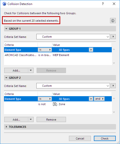
•If any elements are selected, Collision Detection will check only selected elements! See the top of the dialog for feedback on any current selection.


See Define Collision Groups for more information.
4.Set Surface and/or Volume Tolerance values as needed.
See Set Volume/Surface Tolerances for more information.
5.Press Check to run Collision Detection.
6.The Model Check Report opens to show results. Collisions-type problems are listed as such in the Report. Click Info to see the number of Collisions.

As with other problems listed in the Model Check Report, you can view the related elements in the model and create Issues.
See Model Check Report.
Surface Criteria in Graphic Override Rules and Collision Detection
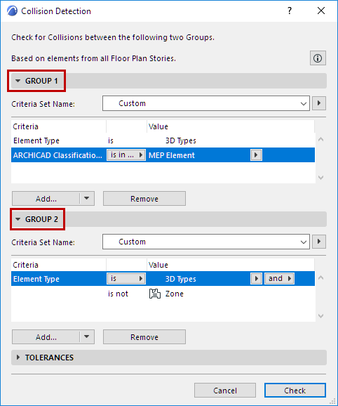
Under Group 1 and Group 2, use the criteria interface to define the collision groups.
•To check collisions between all element types, use the same criteria for both groups.
•To check collisions between 3D elements and MEP elements only, limit one of the groups to elements classified as MEP.
•To use a saved Criteria Set to define a Collision Group: click the Criteria Set Name arrow to list the project’s criteria sets:
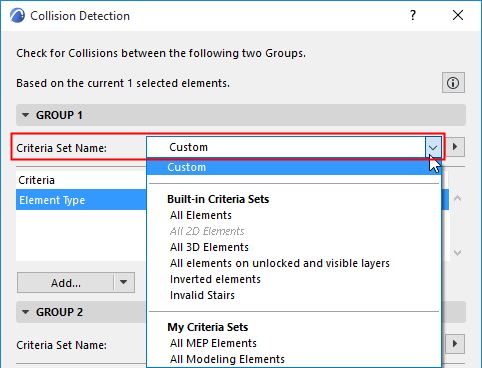
–If you pick a Criteria Set here, its contents will overwrite the Collision Group’s current criteria
–Listed Criteria Sets may be disabled if the set includes criteria not applicable to Collision Detection (e.g. 2D element types, or IFC properties)
See also Predefined Criteria Sets.
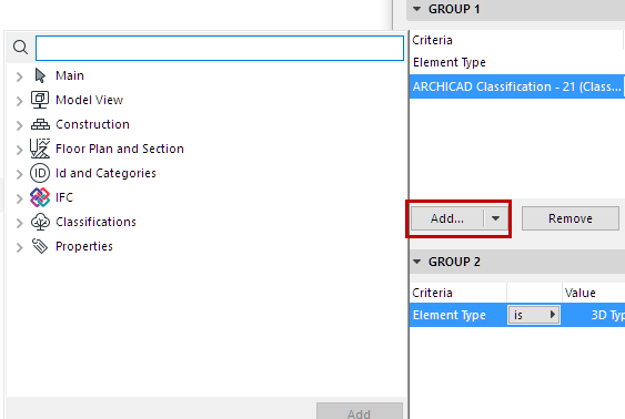
•Click Add to bring up a dialog to choose any Properties and Parameters by which to limit the group.
Optionally, define Tolerances for the volume and surface of elements’ colliding parts.
Elements are considered to collide if the colliding parts’ volume or (if enabled) the colliding parts’ surface area exceeds the Tolerance value.
Note: The units here are those of the project’s Working Units (Options > Project Preferences).
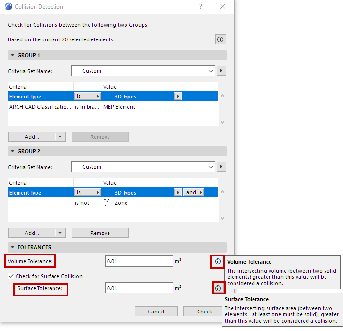
Volume Tolerance
Collision Detection always considers colliding elements in terms of the volume of the colliding parts.
You can set an optional Volume Tolerance: If the volume of the two elements’ colliding parts exceeds this tolerance value, the elements are treated as colliding.
Check for Surface Collision
As an additional option, the Collision Detection function also checks the surface area of the colliding parts. If you enable Surface check and set a tolerance, then elements are treated as colliding if the colliding surface area exceeds this Surface Tolerance value.
Note: If Surface Check is on, it is possible that two elements will be considered as colliding even if the colliding volume doesn’t exceed the Volume Tolerance - because the colliding surface area exceeds the Surface Tolerance. See the example below.
Example: Collision Detection with Volume/Surface Tolerances
Run Collision Detection with the Tolerance settings shown here.
The following two cubes are one cubic meter each. They collide slightly; the overlapping volume is very slight (it doesn’t exceed Volume Tolerance), but the overlapping surface is considerable (it exceeds Surface Tolerance). As a result: Collision Detection counts these two elements as colliding.
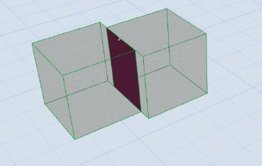
Two Colliding Elements (based on Surface Area of Colliding Part)
Example: Headroom Collision Check
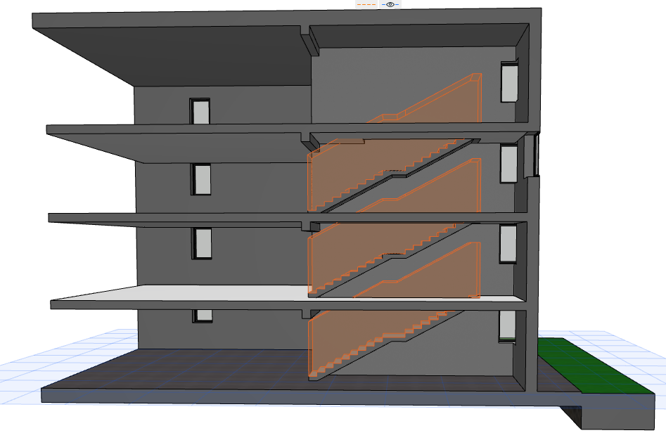
We will check for Headroom collision in this 3D view of the model.
Note: The headroom visibility is turned on at Document > Model View > Model View Options (Stair Options).
1.Go to Design > Model Check > Collision Detection.
2.In the dialog box, define the collision criteria.
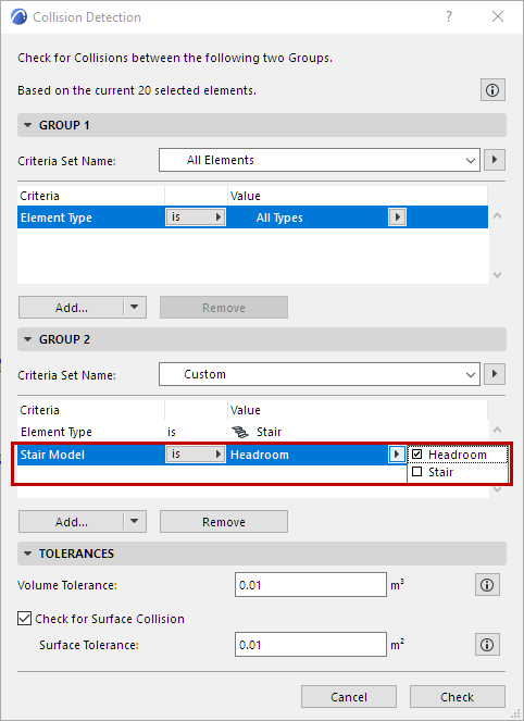
•For Group 1: all 3D elements
•For Group 2: Stairs, considering the Headroom part of the Stair Model.
3.Press Check to run Collision Detection.
4.The Model Check Report opens to show results. Here, for each result you can view the related elements in the model and create Issues as needed.
See Model Check Report.
Exempt Building Material from Collision Detection
Collision Detection takes the elements’ Building Materials into account. Building Materials can be set to participate in Collision Detection, using the checkbox “Participates in Collision Detection” in the Classification and Properties panel of Building Materials, at Options > Attributes > Building Materials.
If this checkbox is turned off, then the Building Material will not participate in Collision Detection.
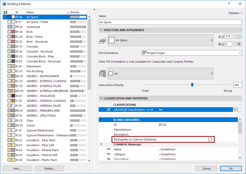
For example, an MEP element (e.g. duct) that runs through a Building Material used as an air gap will not be considered as a collision.