Lines are attributes, defined at Options > Element Attributes > Lines.
Lines types are assigned to Archicad elements in their settings dialogs.
For example, when defining how a Column should be displayed in a 2D window, you will apply different lines for its core outline, for its overhead display and for its crossing symbol.
Edit and manage line types
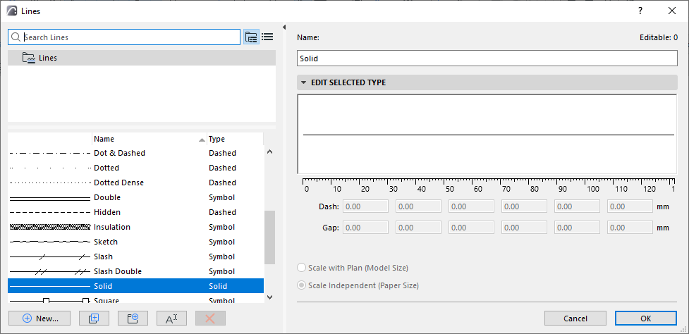
Use the Lines dialog (Options > Element Attributes > Lines) to modify the standard lines (solid, dotted, dashed, etc.) and define customized lines.
For general information: see Using the attribute dialogs.
Choose a Line Type from the left side of the dialog to edit its parameters on the right.
Note: Solid lines are not editable.
1.Click New.
2.Choose a line type:
Set line parameters as described here:
Line Weight
Hairline (default)
By default, all lines are displayed at Hairline width, at one pixel wide.
•You can also enable Bold Cut Lines (View > On-Screen View Options); this will show all Cut lines as bold (two pixels wide, regardless of the line’s true pen weight). All other lines will be Hairline.
True Line Weight
Enable Line True Weight in View > On-Screen View Options. Each line’s pen weight will be displayed based on its pen weight value (defined in the Pens and Colors dialog).
Line Scale
The appearance of the lines on the screen, printer or plotter depends on the following:
•Scale with plan (Model size): Display the line type at the same scale as the model on every output.
Note: Avoid editing a scaled line type if the project scale is different than that of the line type, as it will be distorted.
•Scale-independent (Paper size): Display, plot and print the Line type at a fixed size, regardless of output scale.