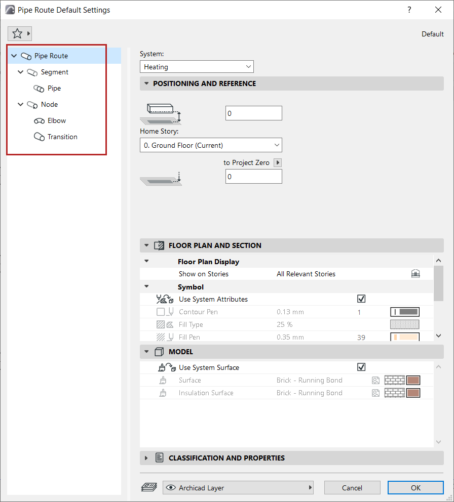
Each MEP Route - Duct Route, Cable Carrier Route, and Pipe Route - consists of a hierarchy of the main Route element, plus its sub-elements: segments and nodes.
Each of the Route Settings dialogs reflects this hierarchy. Use the settings pages to set default options for the Route element and its sub-elements.
Display Settings: Floor Plan and Section, Model Display
MEP Element Settings (Duct, Cable Carrier, Pipe, Elbow, Transition)
As with similar Archicad tools (e.g. Railing), you can customize any particular sub-element. Once a setting is customized and no longer the default, the dialog alerts you that a custom setting is in effect.
1.Open Route Tool Default Settings
2.On the main Route settings page, choose a System. The MEP System defines the Route’s appearance in 2D and 3D. See MEP Systems.
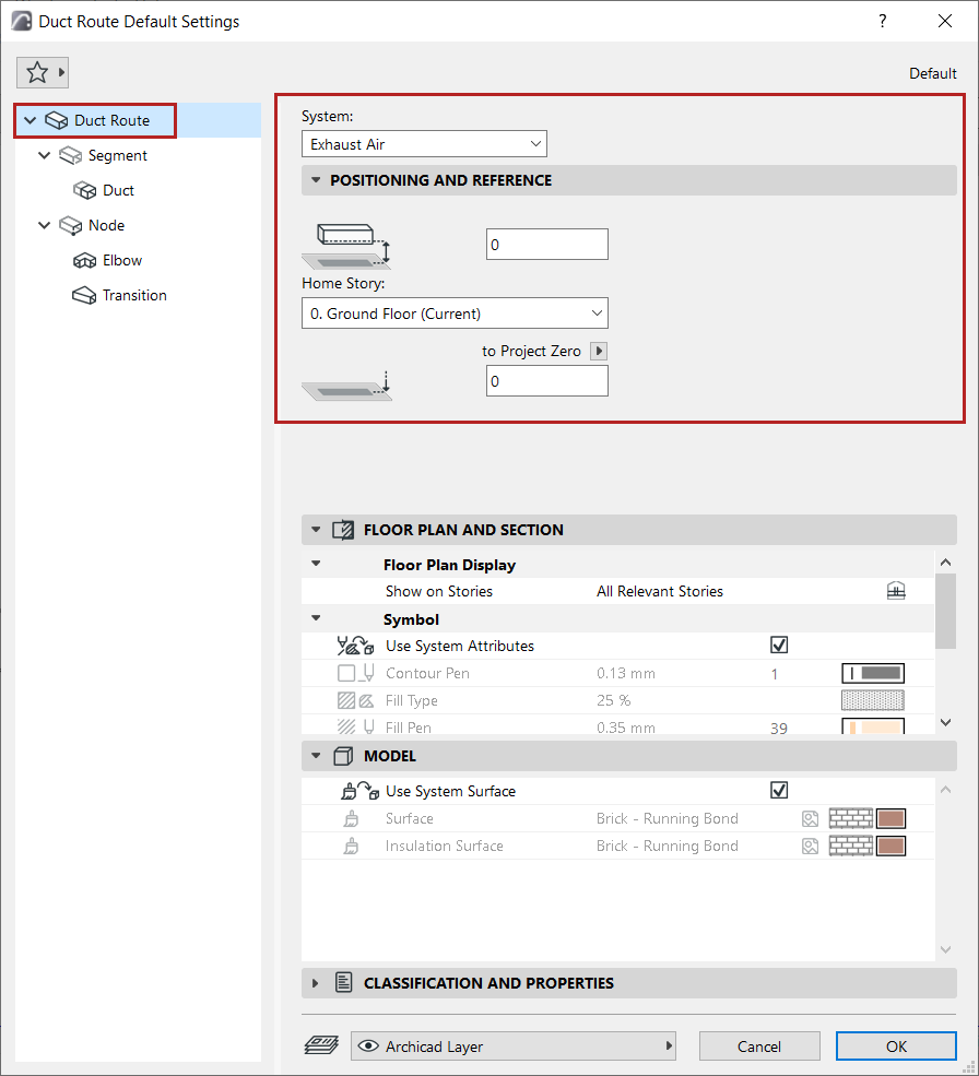
3.Set the Route element’s Positioning and Reference:
•Home story and its offset from that story level
•Bottom offset to the chosen Reference level
Display Settings: Floor Plan and Section, Model Display
The entire Route element has a uniform appearance - you cannot customize the appearance of particular sub-elements.
•Show on Stories: Choose on which stories the MEP Route should be displayed. The default option for all MEP elements is “All Relevant Stories”.
–Straight segments are displayed as cut on the intersected stories
–Other (non-straight) MEP elements that intersect stories do not have cut displays - they are shown either on one story or the other.
•Fills, Lines, and Surface: By default, the Route uses the attributes of the System selected at the top of the dialog. The “Use System Attributes” box (for both Floor Plan/Section and Model) is checked by default:

•To override the MEP System attributes for this Route: Uncheck “Use System Attributes/Surfaces” to activate the local controls and override System settings.
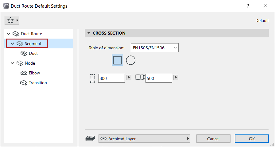
•Choose a Table of dimensions.
Note: Define tables at: Route Preferences.
•(Duct only:) Choose a cross-section: Rectangular or Circular.
•Enter the cross-section dimensions.
Note: You can customize the cross-section of any segment during input - see Change Route parameter on the fly.
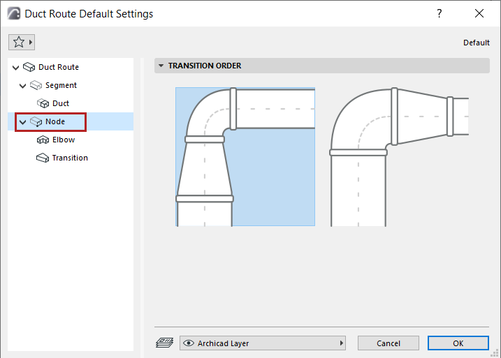
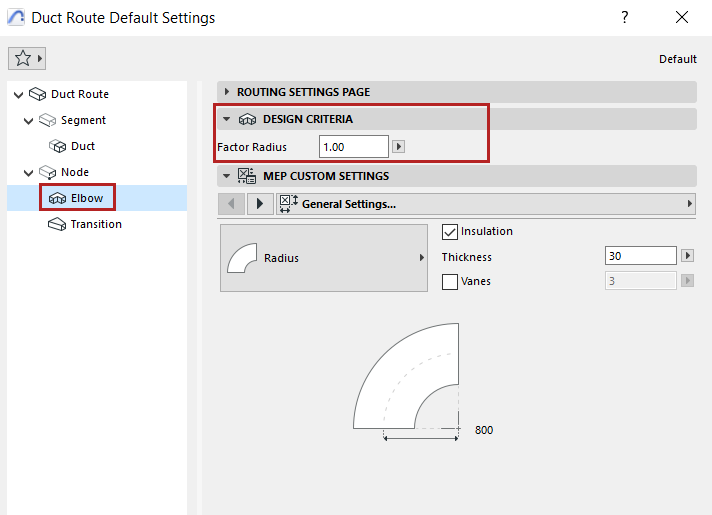
Set the order of the Elbow-Transition elements in the node.
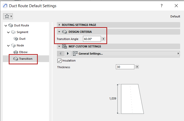
Design Criteria
Defines elbow radius based on this value (minimum: 0.6)
Calculates length of a transition based on this angle: the larger the delta between the two ports, the longer the transition.
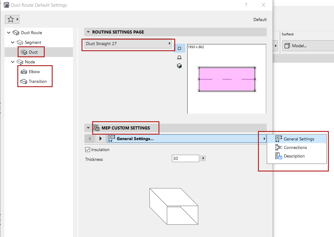
MEP Element Settings (Duct, Cable Carrier, Pipe, Elbow, Transition)
•Choose the MEP element for the segments or the Node parts in this Route
•Set its Custom Settings in the panel below. (Available settings vary depending on the MEP element.)
Insulation
Check to add an insulating layer to the element’s outside surface. Then enter the insulation’s Thickness value.
Set parameters for the connection ports.
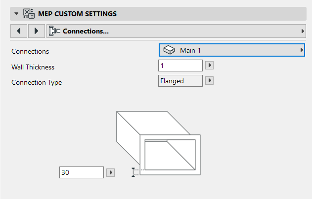
Wall Thickness
Thickness of the MEP element wall.
Connection Type
Choose the appropriate type (e.g. Flanged, Welded, Simple) - this varies depending on the Route type. Enter a width/diameter as applicable.
To use a different Connection Type for the second port:
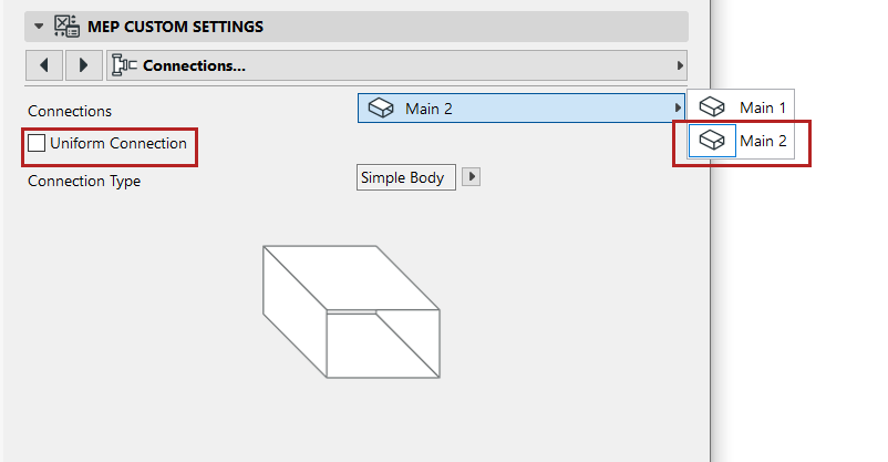
1.Use the pop-up to switch to the second port
2.Uncheck the “Uniform Connection” box
3.Edit the parameters of the second connection
•Choose the MEP element for the elbows and transitions in this Route
•Set their Custom Settings in the panel below.