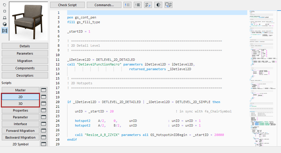
Available from the GDL Object Editor.

2D View
Shows the object’s Floor Plan symbol.
If there is a 2D Script defined, the 2D View will be calculated according to the 2D Script, even if the 2D Symbol window contains drawing elements. However, the 2D Script can refer to 2D Symbol fragments.
3D View
Shows the object’s 3D symbol.
In this window you can see the 3D view of the GDL Object converted from the 3D Script that refers to the current Parameter values. Use the View > 3D View Options > 3D Styles dialog box or the 3D Navigation Palette to adjust its view settings.
The 2D symbol and the 3D description are automatically linked to each other in the GDL Object. There are no built-in safeguards against geometric incompatibilities between the two components. The most common incompatibility error occurs when the 2D symbol and the 3D shape have different positions or orientations with respect to the origin.
To avoid this problem, follow these steps:
1.Activate the 3D View of the GDL Object.
2.Choose Top View in View > 3D View Options > 3D Projections Settings > Parallel Projections, and set the angle to 270°.
3.Choose Edit > Select All, then Edit > Copy. Activate the GDL Object’s 2D Symbol window and choose Edit > Paste. This will place the top view of the object (as a wireframe or hidden line) into the symbol window. It should match the dimensions and position of the 2D symbol.
4.Choose Undo once you have verified that the symbol matches the 3D view. This will remove the 3D lines.
You can use this feature to have Archicad create the 2D symbol for you. You will only need to add additional hotspots, lines, etc. The procedure is the same for Doors and Windows, with the following modifications:
•Choose Side View instead of Top View (the angle should still be 270°).
•A mirrored view will be placed. Select the placed lines and mirror them across the reference line of the wall.
Note: When you place a wireframe view, redundant lines are removed. Using Hidden Lines will give you an accurate view, but underlying lines will be hidden.
You can also ensure compatibility between the 2D plan symbol and the 3D model of a GDL Object by writing a parametric description in GDL for the symbol.