MEP System Browser (Duct Routes)
Use the MEP System Browser (Window > Palettes) to view and manage your ventilation routes. The MEP System Browser provides runtime calculation and displays the data (volume flow, velocity) in table form. Based on the settings of the connected MEP elements, you can see air flow calculations and resizing requirements for each system.
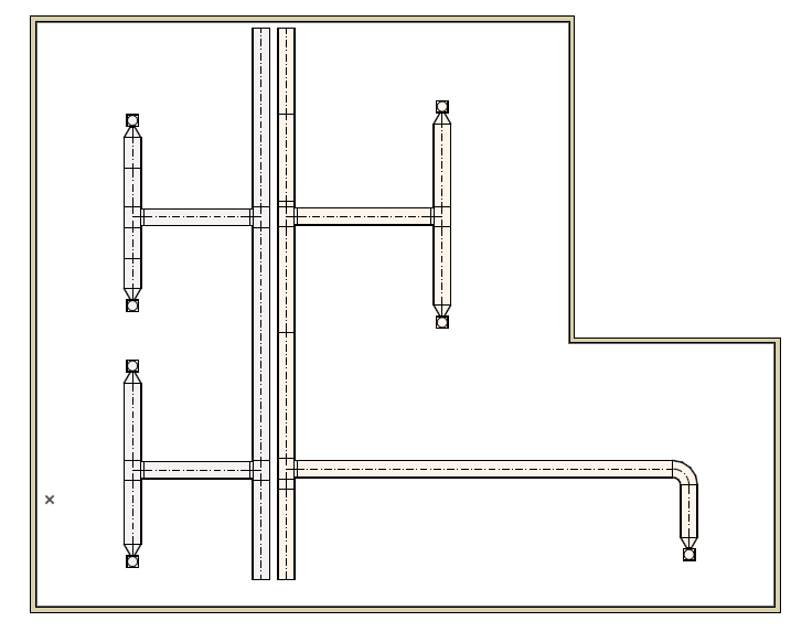
1.Create Ventilation system using Ductwork elements in Archicad
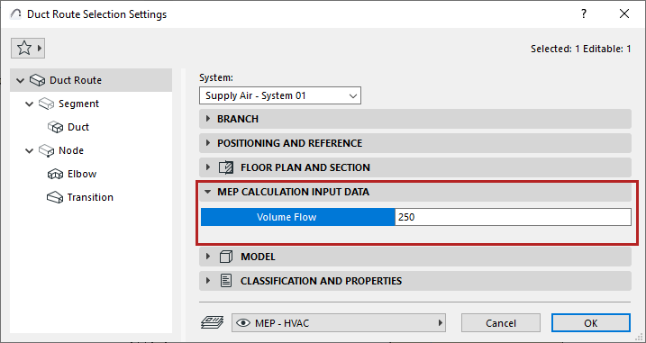
2.Enter Volume Flow values for Duct Route and Duct Terminal elements, in their settings dialogs or the Info Box

3.Open MEP System Browser
•from Window > Palettes menu, or
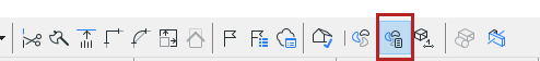
•use the shortcut from the MEP toolbar
4.Select System start point: In the model, select an element to be the System start point. This element’s port represents the start of the system - e.g. where the air will come from.
•The start point element should be the open end of a ventilation route, or a connected Equipment or Accessory (the starting element cannot be a terminal).
•The selected element should have an assigned MEP System attribute that is used with Ductwork.
Note: To see open ends and open connections in 2D views, turn on Open MEP Connections at View > On-Screen View Options.
5.Add System to Browser: In the System Browser, click [+] to add the new System. Its name corresponds to the route’s MEP System. You can add any number of systems to the browser.
•If the [+] control is greyed out, it means the selected starting element is not valid.
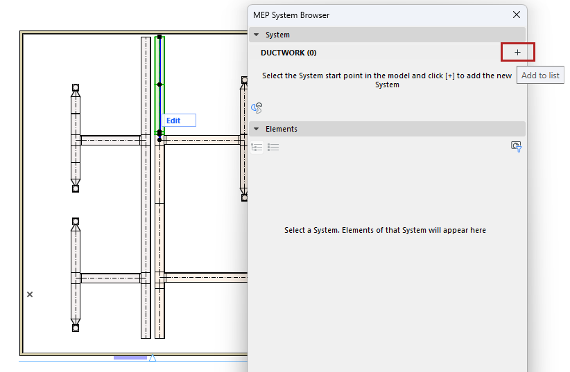
•If you later eliminate the System start point (for example, you add a terminal to the open end), the System is deleted from browser, because it has no open end. An alert will allow you to either undo this, or else continue - in that case, you can later add the System to the browser by using a different start point.
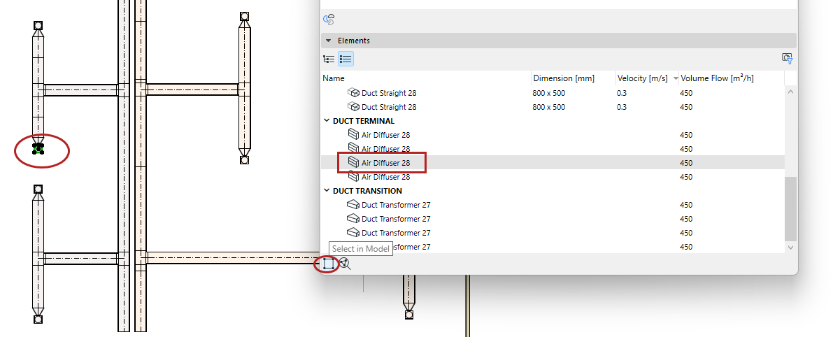
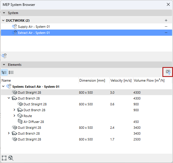
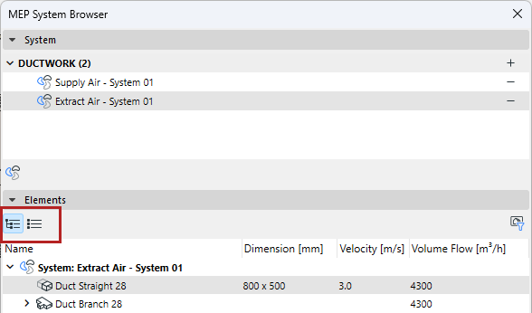
6.Check System calculations in the browser: select a System in the top half of the browser to see calculations for its elements, listed at the bottom.
•Volume flows are added up to the System start point
•Velocity is calculated for the routes and segments
These data are based on element dimensions and the Volume Flow data you entered for terminal elements.
.
Note: To show data only for elements visible in the current view, filter by “Visible Elements Only”. For example, use this to hide data for elements hidden by Renovation Filter.
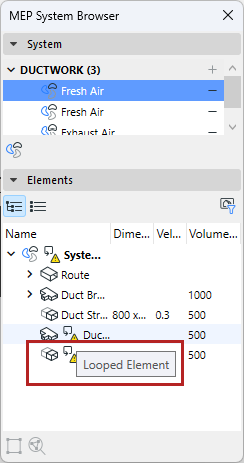
Note: When loops occur in the system, the volume flow and velocity can’t be calculated. Such loops are marked in the System Browser.
Optimize Duct dimensions
Based on the data shown in the System Browser, use the Duct Optimizer tool to adjust dimensions as needed.
See Duct Size Optimizer.
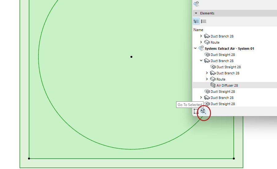
Navigate in System Browser
•Use the shortcut to the MEP System dialog
•View data in a hierarchical tree structure, or as a flat list (switch views using the icons)
•In flat list view: click a column header to sort values in ascending/descending order

•Use Select in Model to find a Browser item in the model
•Use Go to Selected to zoom to the Browser item in the model