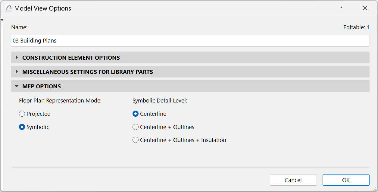
To access this panel, go to Document > Model View > Model View Options.
These MEP options control the appearance of MEP elements on the Floor Plan. For these settings to take effect, each element’s Floor Plan display option (at Element Settings) should be set to “By MVO”. (See Display of Route Element: Floor Plan and Section, Model Display).
MEP distribution elements can be represented with the following Model View Options:
•Centerline
•Centerline + Outlines
•Centerlines + Outlines + Insulation
A distribution element that goes through a Floor Plan Cut Plane is shown with a cut symbol.
Terminal, Accessory and Equipment use built-in symbols - but you can also create custom MEP symbols.