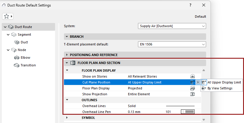
Display of Route Element: Floor Plan and Section, Model Display
Available with Archicad Collaborate
Set the floor plan display for the MEP route.
Show on Stories
•Choose on which stories the MEP Route should be displayed. The default option for all MEP elements is “All Relevant Stories” (where the route is physically present).
Cut Plane Position
Choose how to display the MEP Route, based on Floor Plan Cut Plane settings.
Note: This control applies only affects supported MEP elements - such as those from MEP Library.libpack. Other MEP elements have a uniform appearance, regardless of which floors they intersect.
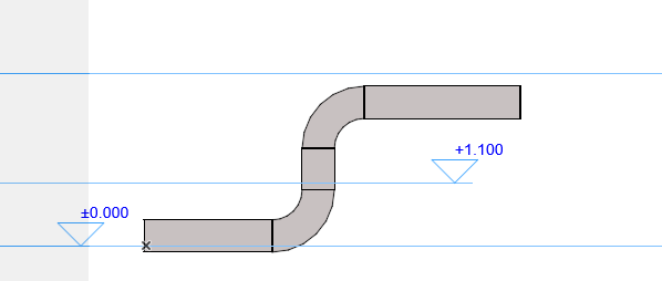
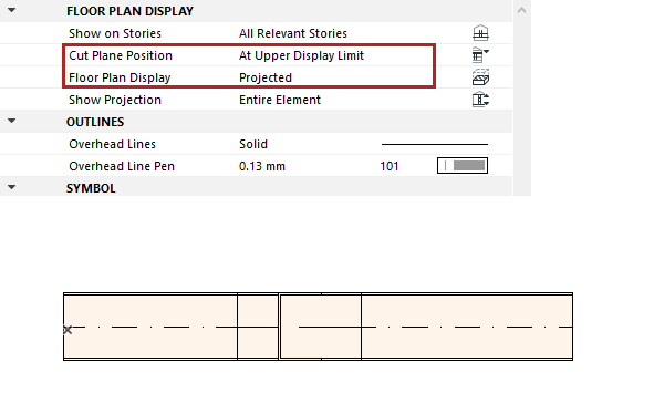
For example, this Route shown can have different Floor Plan displays:
•Upper Display Limit: Cut the MEP route at the upper display limit (as set in Floor Plan Cut Plane)
•By View Settings: Cut the MEP route at height of the Floor Plan Cut Plane
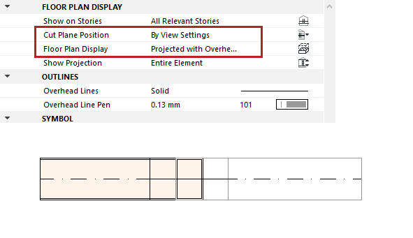
Floor Plan Display
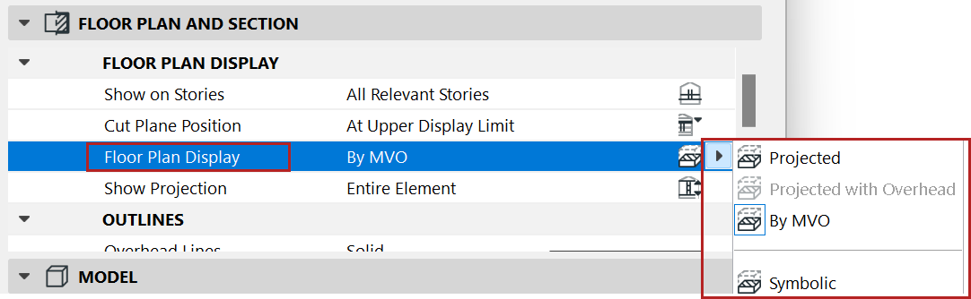
•By MVO: Applies the setting at Model View Options, in the “MEP Options” panel. (See MEP Options.)
•Projected: From Floor Plan Cut plane to “Show Down to” plane + cut symbol
•Projected with Overhead: From Floor Plan Cut Plane to “Show Down to” plane + cut symbol, and from “Show up to” to Floor Plan Cut Plan (available if Cut Plane Position is set to “By View Settings”)
•Symbolic: From “Show Down to” to “Show up to”, using outlines with projected lines, axis
•For projection options: see Show Projection
Symbol: Fills, Lines, and Surface
By default, the Route uses the attributes of the System selected at the top of the dialog. The “Use System Attributes” box (for both Floor Plan/Section and Model) is checked by default. System attributes are defined at: MEP Systems.
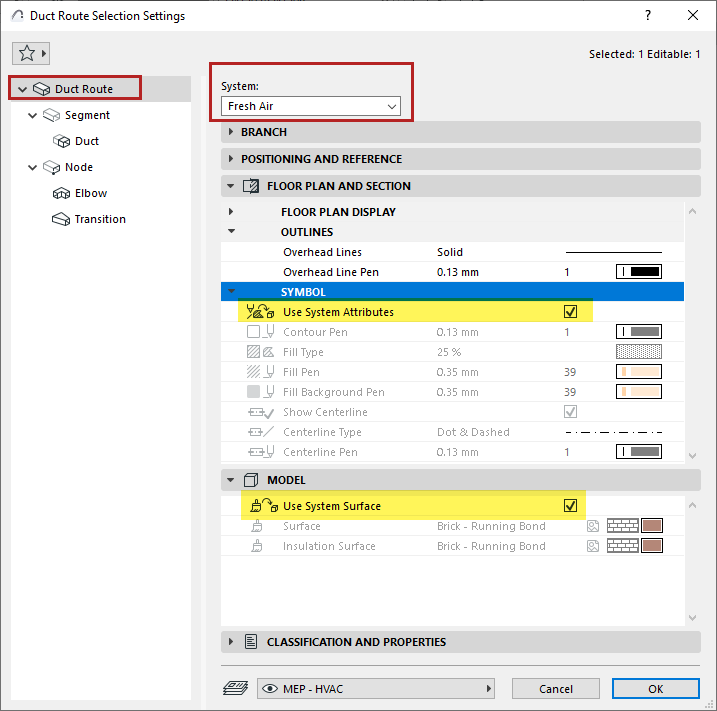
•To override the MEP System attributes for this Route: Uncheck “Use System Attributes/Surfaces” to activate the local controls and override System settings.