Ruled Shells
A Ruled Shell requires two separate profiles in any two planes.
Each of the two profiles, like line-type elements, consists of segments and intermittent nodes. To create a ruled Shell, Archicad will draw connecting lines between the respective segments and nodes of each of the two profiles. The Shell is then “grown” onto the resulting geometry.
Ruled Shell Morphing
The logic (called “Morphing rules”) by which the two profiles are connected can take two forms. Choose the desired icon from the Info Box or the Geometry and Positioning Panel of Shell Settings, with the Ruled Construction method selected.
- Paired: Profiles are connected by
mapping each segment/node on one profile to a single segment/node on the other profile. If
the segments/nodes cannot be matched up one-to-one, then they are paired off
proportionately.
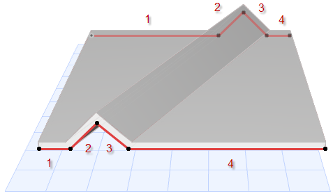
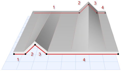
- Smooth: Profile polygons are
connected by joining the respective segments that are of proportionate lengths, without
calculating the position of nodes. This may be advantageous if you have drawn the profiles
based on a spline, which creates a large number of seemingly random nodes.
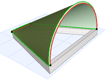
For more examples, see Sample Workflows for Shell Creation.