Place Line Load
Line Loads can be input on 1D or 2D Members.
- Activate the Line Load tool.
- In Tool Settings or Info Box: Select a Load Case for your new Load element (see Load Tool Settings).
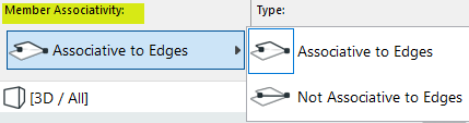
- In the Info Box: Choose whether the Load should be associative to the edges or not. (This is relevant if you are placing the load along a 2D Member edge. See Line Load: Edge Associativity.)
- As you move the cursor, the potential host element (Structural Analytical Member) is highlighted. You also get a preview of what the Load will look like after placement.
If you are hovering over multiple host elements, use Tab to cycle among them until the right one is highlighted.
- Click on a Member to specify the start point.
- Drag the cursor, then click to place the Line Load.Note: Loads are visible only if they belong to the currently visible Load Case. If you try to place a Load element that does not belong to the currently visible Load Case, you get a notification.
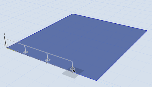
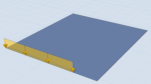
Placing a Line Load
Place Chain of Line Loads on 2D Member Polygon
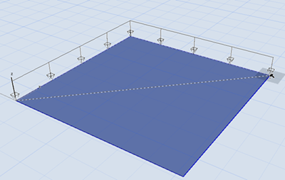
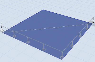
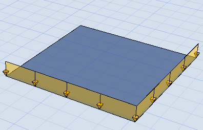
Line Loads on All Edges (Shortcut)
Use the Magic Wand (space + click) to create Line Loads on all 2D Member edges.
Line Load: Edge Associativity
Before placing a Line Load, choose its Edge associativity setting in the Info Box. This is relevant for Line Loads on the edge of a 2D Member. (It does not affect Line Loads that do not coincide with a Member edge.)
When you edit the Member edge:
- Associative Line Loads will follow any changes in edge geometry.
- Non-associative Line Loads will not follow changes in edge geometry (but when the Member is dragged, the Line Loads move too).
If you place a Line Load on the edge of an Opening element (e.g. within a Slab), the Load cannot be associative.
In contrast, a Line Load on the edge of a hole can be either associative or non-associative.