Beam Flight Structure
These settings are available if you chose a Beam Structure type for the Flight.
Beam Structures are GDL elements: Choose a component from the pop-up to serve as the Beam support.
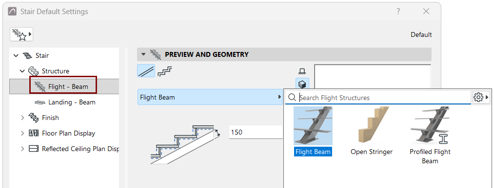
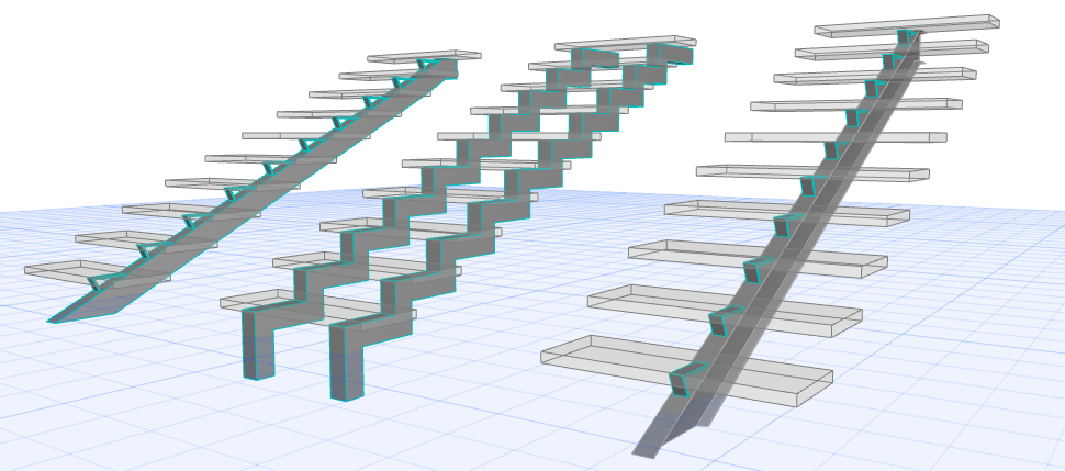
Components include a general Beam; profiled Beam; and Open Stringer (see below).
Use Open Stringer (Beam Flight Structure)
An “Open Stringer” structure is available from the Beam - Flight component pop-up list.
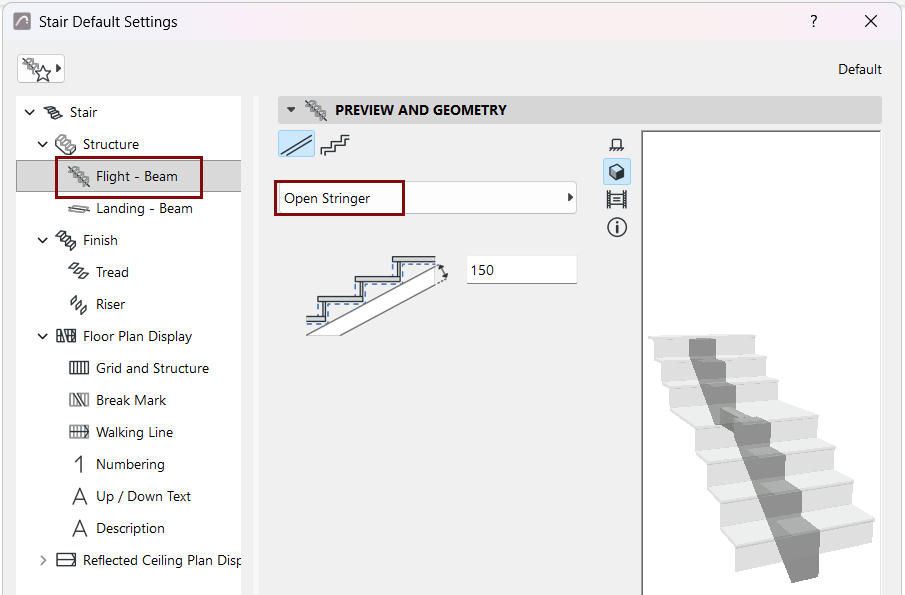
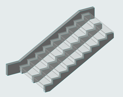
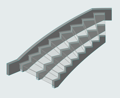
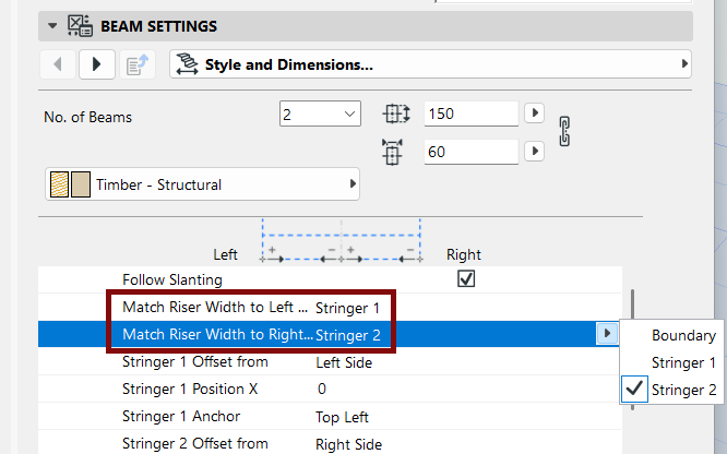
Use Beam Component Settings to position the Stringers. Note the options to match Riser Width to either the Stringers (if they are offset) or the Stair Boundary.
Choose Shape
In Beam Flight Settings, choose a Beam Structure shape: either flat or stepped. Profile components are also available.
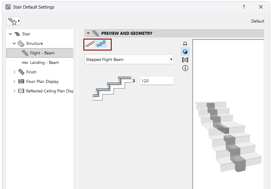
Below, enter a value for the Beam thickness. Note the feedback in the Preview window.
Beam Settings
Use this panel with its tab pages to set the Beam component’s settings.
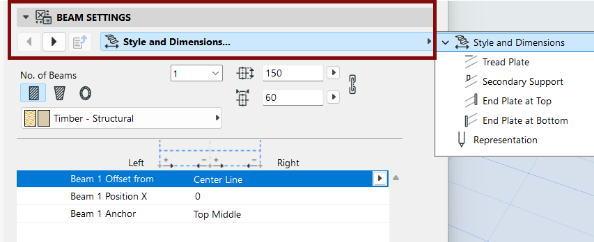
Beam Anchor Point
The Anchor Point is at the top of the beam: Choose Top Left, Top Middle or Top Right.
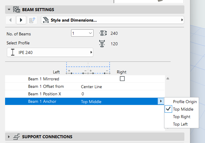
For Profile definition, see Profile Origin in Profile Editor Window.
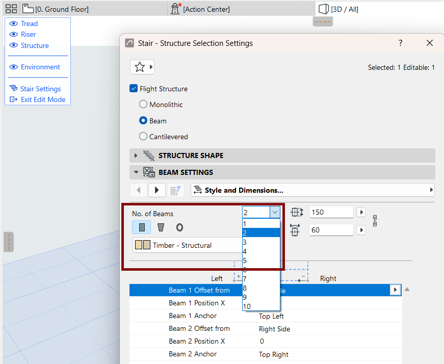
Set Number of Beams
Use this control (Style and Dimensions page of Beam Settings) to add multiple Beams (up to 10) to serve as the Stair’s support structures on all flights.
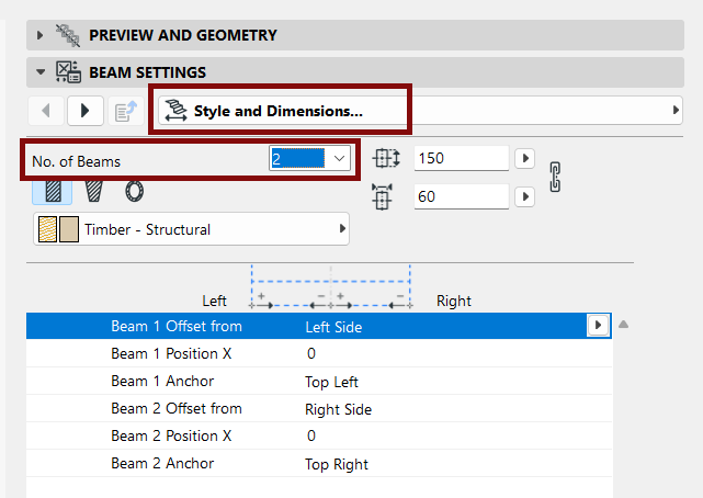
Note:
- Number of Beams must be set (on separate Settings pages) for both Flight and Landing.
- In Edit mode, you can customize the number of beams per Flight or per
Landing, as needed.
Beam Attributes and Representation
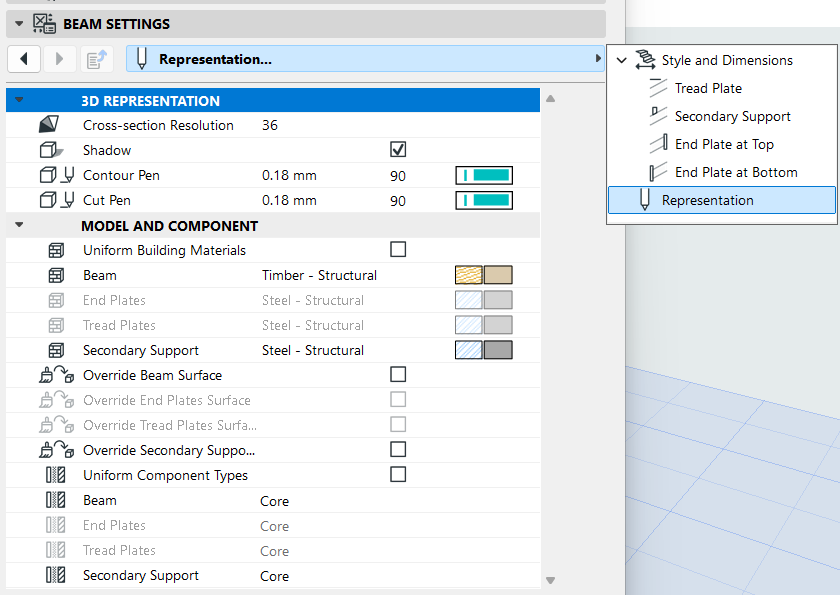
Depending on the Beam component, set its Building Material and/or choose a Profile. Adjust its values as needed.
Note:
- Beam attributes must be set separately for Flight and Landing.
- The “Uniform Building Materials” checkbox enables a single Building Material for the listed Beam components (e.g. Beam, End Plates, Secondary Support).
Define components as Core/Finish/Other
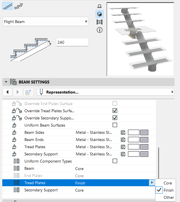
In the Representation section of the Settings dialog: set the components as Core/Finish/Other. (When editing Beam, Cantilever, and Stringer structures: uncheck the "Uniform Component Types" to set each component separately.)
Defining component types in this way allows you to control their display via Partial Structure Display. For example, to display structure-only coordination views, choose "Core only" as the view's Partial Structure Display setting. This will hide stair components that are defined as "Finish" or "Other".
Add Tread Plates and/or End Plates to Beams
See also Add Tread Plates at Beam Landing.
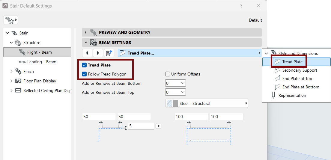
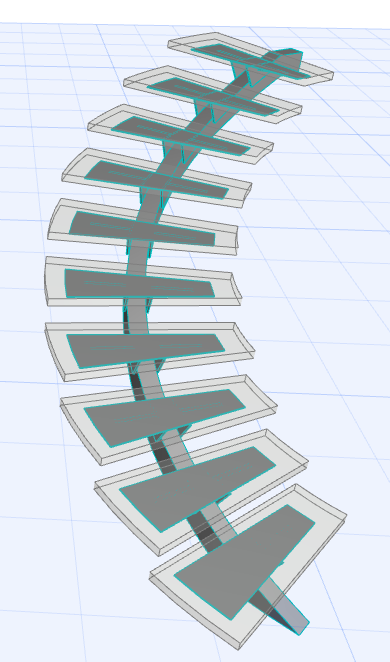
Tread Plate Follows Tread Polygon
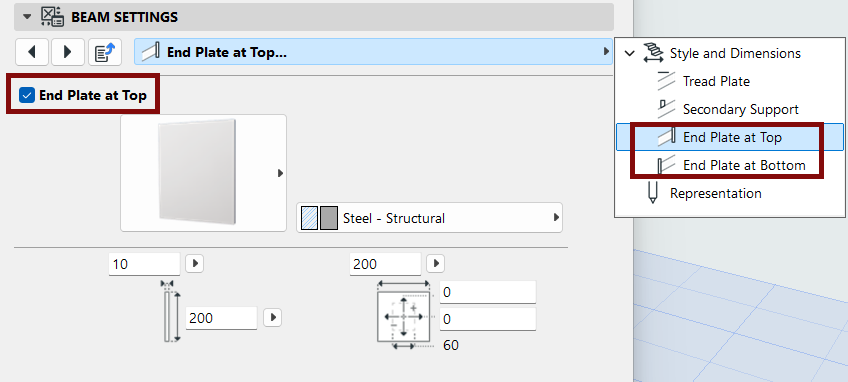
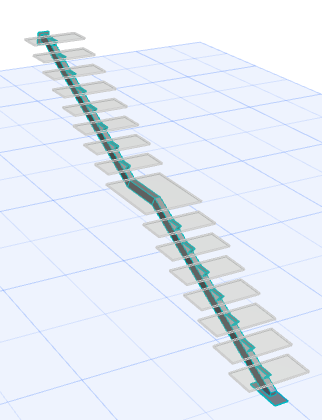
End Plates at Top and Bottom
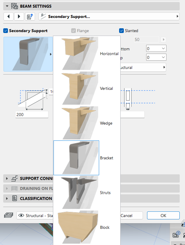
Add Secondary Supports to Beams
For a Beam Flight Structure, you can add additional components to support the Treads.
Go to the Secondary Support tab page, and enable the Secondary Support checkbox.
From the pop-up, choose and set the desired component.
You can control the number of supports at either end of the beam, using the Add or Remove pop-ups:
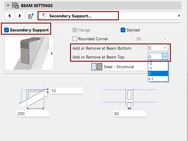
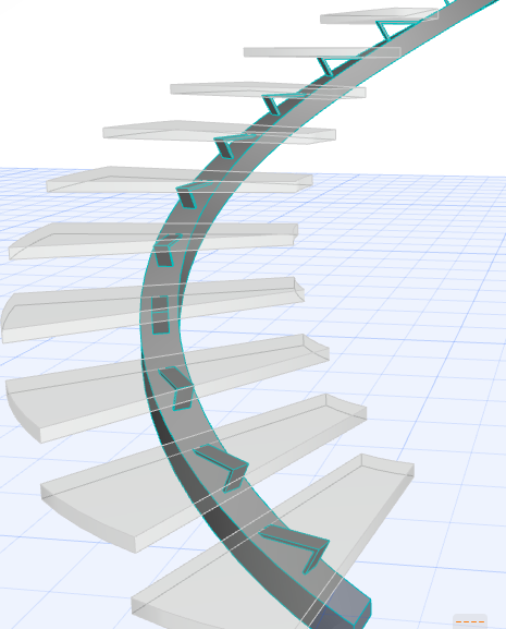
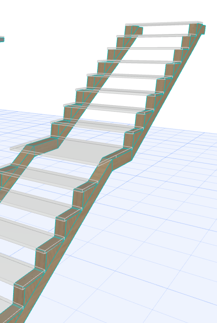
Beam Flight Support, with Secondary Supports