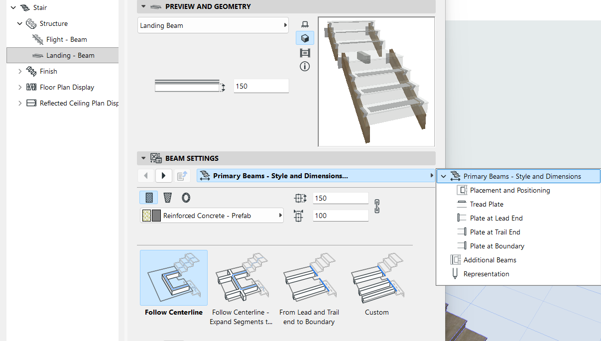
The Primary Beam generally follows the Stair Centerline, but you
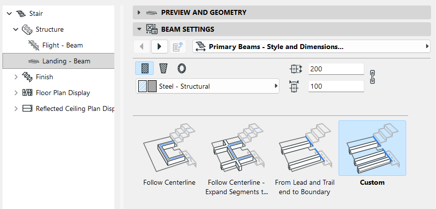
can also choose a different Beam path (use the Primary Beams - Style and Dimensions tab
page):
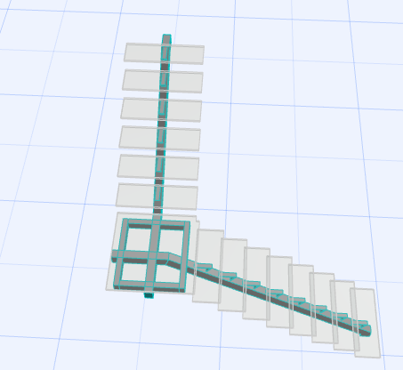
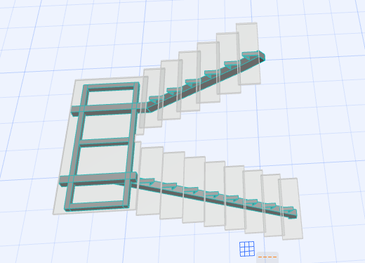
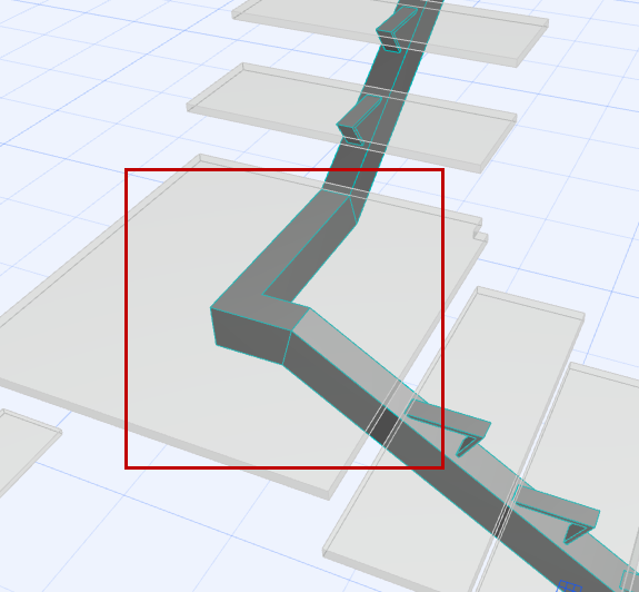
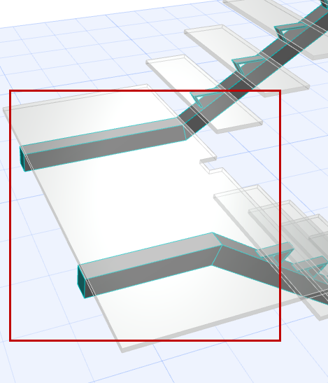
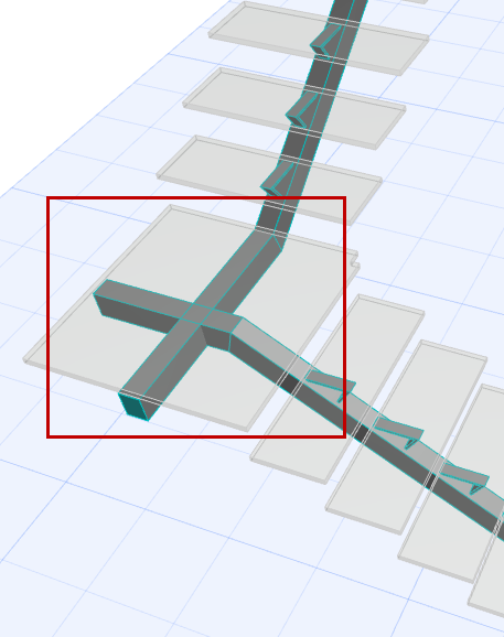
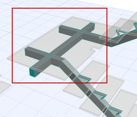
PRIMARY BEAMS POSITION
Figure 1. Follow Centerline
Figure 2. Lead/Trail End to Boundary
Figure 3. Follow Centerline - Expand to Boundary
Figure 4. Follow Centerline - Expand to Boundary
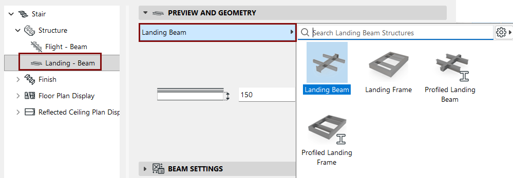
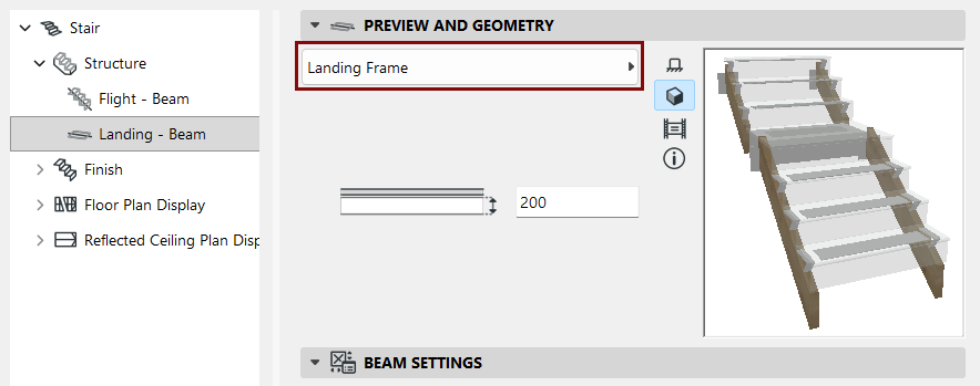
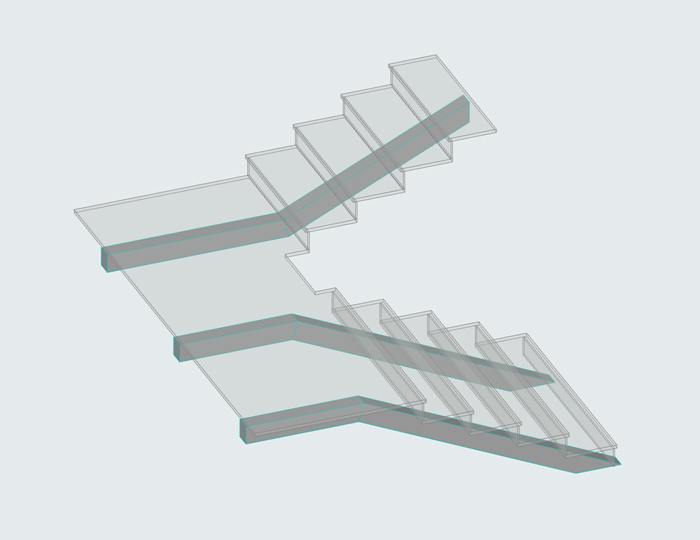
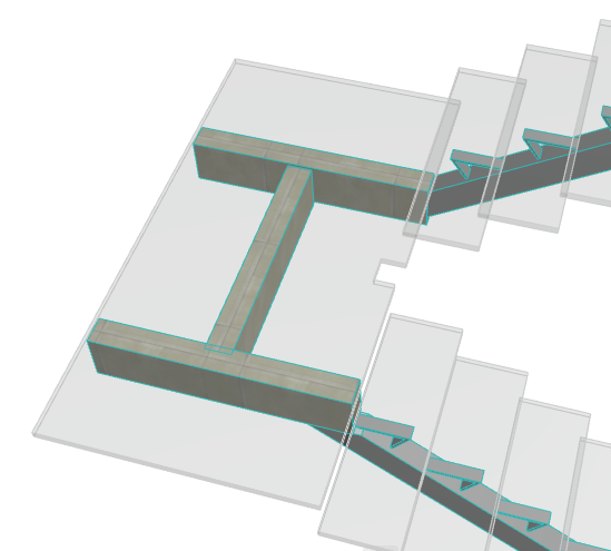
Landing Frame (Primary Beam)
You can choose a Frame to support the Stair Landings. Like other primary
beams, the Landing Frame component connects automatically to Flight support, as defined at
Flight Structure Settings.
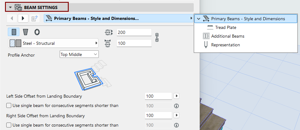
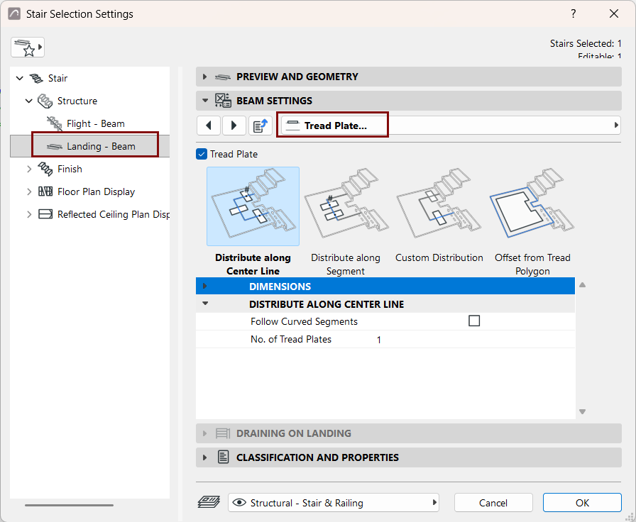
Use Beam Settings to configure the chosen Landing Frame:
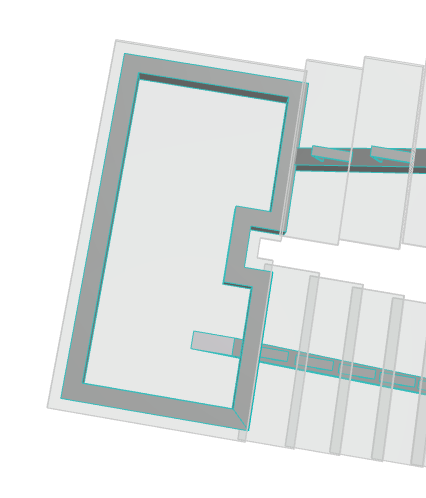
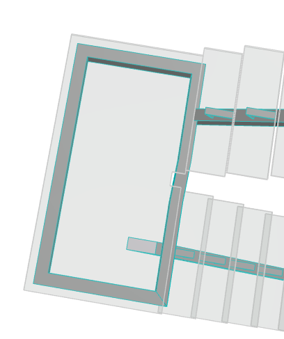
By default, the Landing Frame follows the Landing outline.
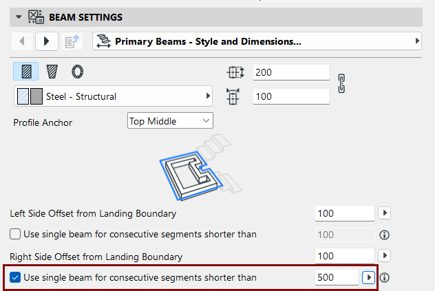
However, you can use Beam Settings to adjust the outline so it ignores
Landing segments that are shorter than a certain length:
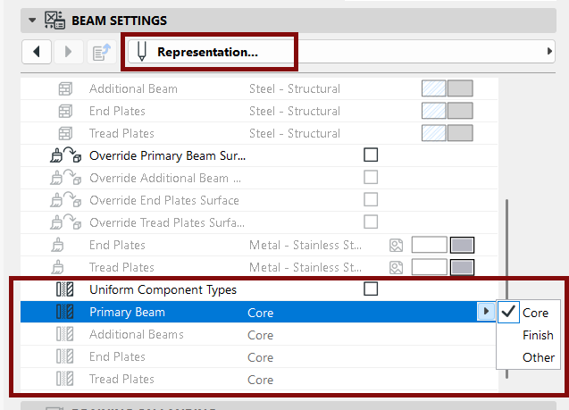
Define components as Core/Finish/Other
In the Representation section of the Settings dialog: set
the components as Core/Finish/Other. (When editing Beam, Cantilever, and Stringer
structures: uncheck the "Uniform Component Types" to set each component
separately.)
Defining component types in this way allows you to control their display via Partial
Structure Display. For example, to display structure-only coordination views, choose
"Core only" as the view's Partial Structure Display setting. This will hide stair
components that are defined as "Finish" or "Other".
Partial Structure Display of stair components is supported in views based on the 3D
model (e.g. Sections). In Floor Plans and Ceiling Plans, stairs are displayed as
symbols and are not affected by Partial Structure Display.
Note: For profile components, set their type in the Profile
Manager.
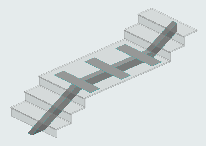
Custom Landing Beam (Primary Beam)
Use this function when the Stair Flight below the Landing uses a
different number of Beams than the Flight above the Landing. (You can define beams for each
Flight structure separately in Edit mode.)
To place a custom Landing Beam:
Choose Custom from the Beam Settings page (Primary Beams - Style and
Dimensions tab page).
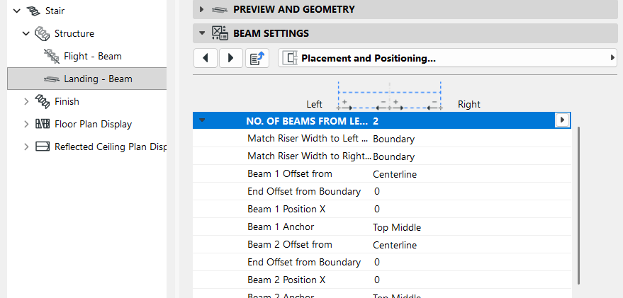
Switch to the Placement and Positioning tab page.
Enter the number of Beams to place.
Enter position and offset values for the custom landing Beam(s).
Since these custom Beams are Primary Beams, they can connect to the
Flight supports.
Add/Edit Secondary Beams
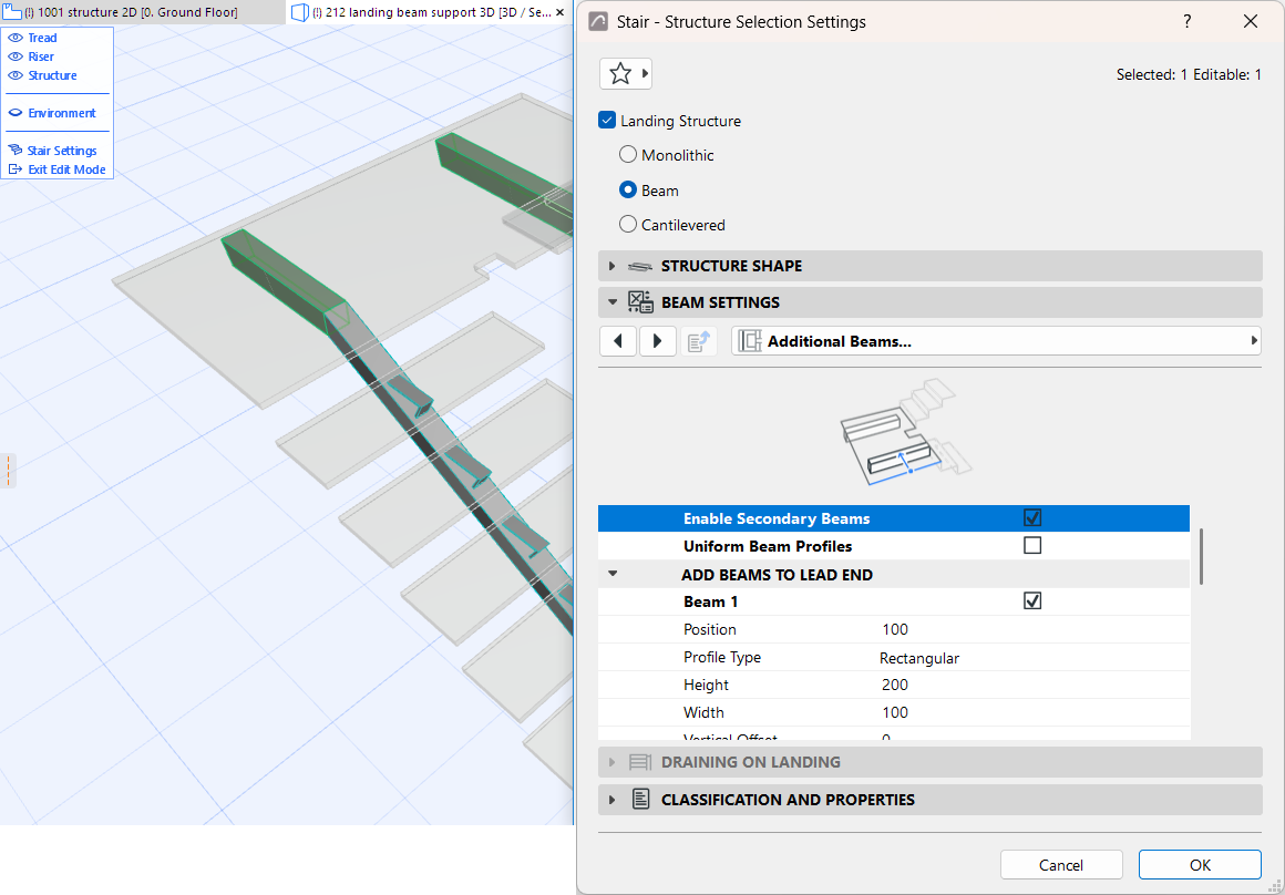
To add additional (Secondary) Beams, you must use Edit mode. (Secondary
Beams are positioned to an existing Landing’s geometry, and thus must be added to a placed,
selected Stair.)
Select the Stair and enter Edit mode.
Select the Landing Structure, and open Structure Settings.
In the Beam Component Settings panel, open the Additional Beams
tab.
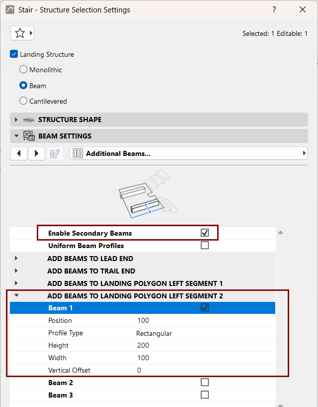
Check Enable Secondary Beams (if it is not checked already).Figure 5. Add Secondary Beams in Edit Mode
Use the checkboxes and settings to add Secondary Beams to one or more
segments of the Landing polygon.
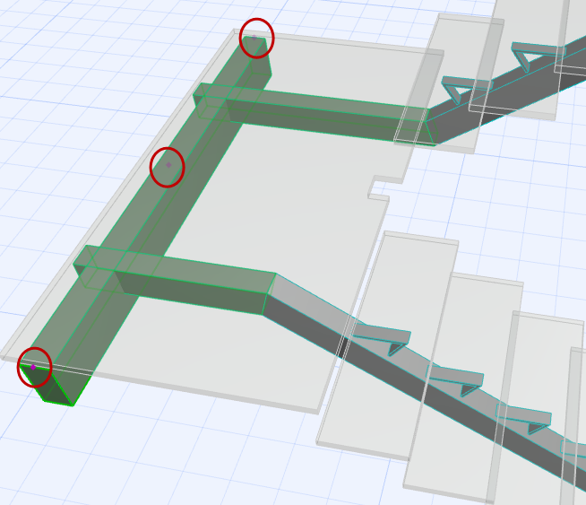
The secondary beam(s) are placed. Use Edit mode to stretch and move them
as needed, using the editable hotspots.