Set Orientation of Vector or Symbol Fill Patterns
Use the Orientation Method controls to manually define or change the orientation of a vector or symbol fill pattern.
Where to Choose a Fill Orientation Method for an Element
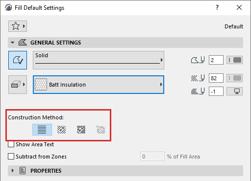
- For Fill elements that use a vector or symbolic cover fill, use
the “Construction Method” options in the General Settings panel of Fill Settings.
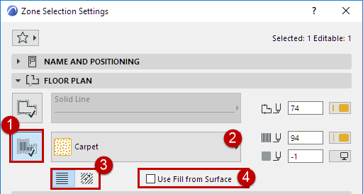
- For Zones that use a vector or symbolic cover fill, use the
radio buttons in the Floor Plan panel of Zone Settings.
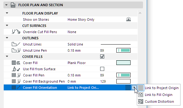
- For Cover Fills assigned to a Beam, Column, Mesh, Slab, Roof,
Opening, Morph or Shell, use the controls under Cover Fill in the Settings dialog box.
See also Assign a Cover Fill.
- For cut fills used in components of complex or composite elements, Fill Orientation settings derive from their Building Material.
Fill Orientation Methods
Place Vector Fill with Linked Pattern
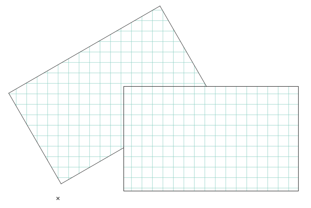
Link to Project Origin
With this option, hatching orientation is always orthogonal from the Project Origin, independently of the transformations made on the element.
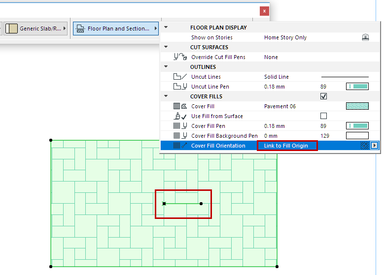
Link to Fill Origin
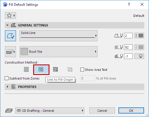
Use the Link to Fill Origin to fine-tune the angle of the fill pattern.
A single handle appears on the placed fill to show the orientation of the fill.
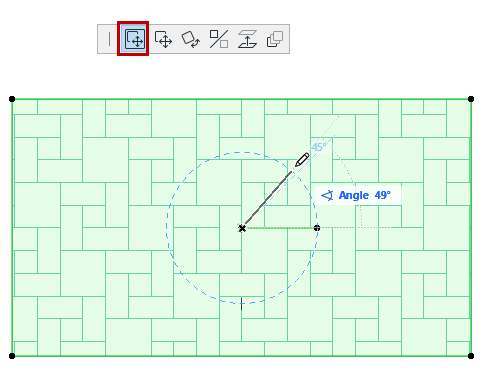
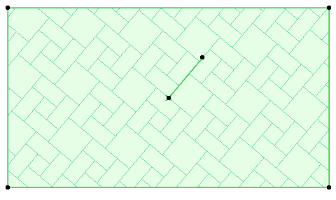
Now drag the Fill Handle to realign the fill pattern as needed. Make sure the Move Sub-Element icon is active on the pet palette.
Place Vector Fill with Linked Pattern
- In Fill Settings, set the Link to Fill Origin option.
- Place the fill polygon.
- Select the fill.
- Drag either end of the fill handle to define the origin and direction
of the fill pattern.
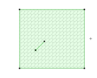
Note that the handle does not necessarily have to be located inside the Fill. You can drag the handle out of the body of the fill after placing it.
3D Distortion
Available for Beam, Column, Shell and Morph.
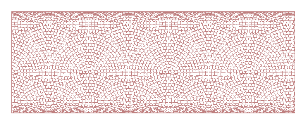
This option distorts the cover fill, simulating the 3D view of a curved surface on the Floor Plan.
Custom Distortion
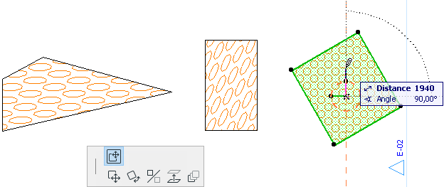
This option displays a double fill handle at the fill origin.
Manipulate the hatching pattern by modifying the length of either handle and the angle closed by the two handles.
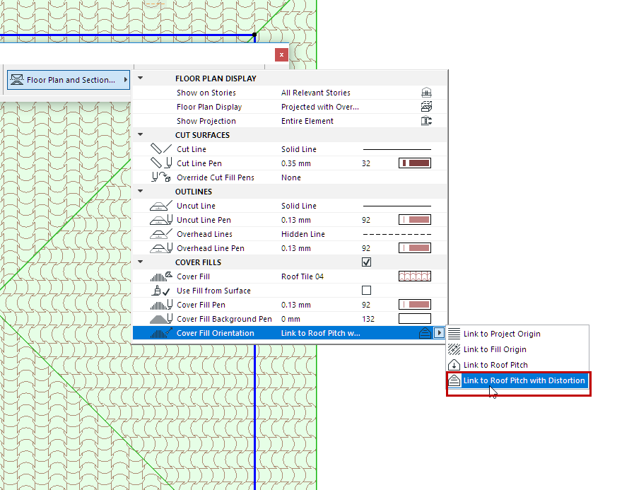
Distorted Fill for Roofs
Set the Roof’s cover fill Orientation to Link to Roof Pitch with Distortion.
The cover fill is automatically distorted to follow the Roof pitch.
Symbol Fills as Skins of Composite Elements: Fit to Skin
If a composite element includes a symbol fill as part of the Building Material, you can adjust that fill to “fit to skin”, so that the fill pattern is adjusted to the shape of the skin. This is especially useful when modeling soft insulation, plywood, metal decking or any directional fill.

To do this, use the controls in the Building Materials dialog box (Options > Element Attributes > Building Materials.)

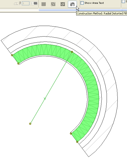
Radial Distortion (Symbol Fills only)
The Radial Distortion Fill construction method (Fill Tool) lets you graphically adjust the vector’s radial distortion. This is available only for a selected symbol fill and only if:
- the symbol fill was used as a skin of a composite or complex structure; and
- the skin’s Fill Orientation was defined as Fit to Skin in its Building Material; and
- you have selected this symbol fill after exploding a curved composite/complex wall.
Here is a curved composite wall with a symbol fill (orientation: Fit to Skin) as one of the skins, after the composite wall has been exploded. Each fill can now be selected separately. The symbol fill displays a fill handle and the Distorted Radial Fill construction method is available. Adjust the fill handle to adjust the fill’s distortion or the pattern’s origin as needed.