Shell Tool Settings
Note for MEP Designer users: Shells and Shell Settings are visible, but cannot be created or edited.
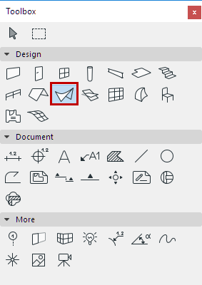
For a description of generic settings common to all tools in the Toolbox, see Working in Tool Settings Dialog Boxes.
For general information on how to create and edit shells, see Shells.
Shell Geometry and Positioning Panel
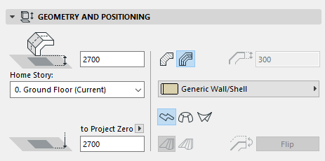
Reference Line Offset to Home Story: Enter a value here for the elevation, measured to the Home Story, of the initial point of
- the Shell’s extrusion vector (for an extruded Shell), or
- the Shell axis (for a rotated Shell), or
- the Shell’s first profile (for a ruled Shell).
These reference points are distinguished by a highlighted hotspot on each selected Shell.
Home Story
See Home Story.
Reference Line Elevation [to Reference level]
Elevation of the Shell’s starting point (reference point) as measured from the Reference level (by default, this Reference level is Project Zero). Click the pop-up arrow to change the Reference level, if needed.
Note:
Shell Structure
Click one of these icons to define the Wall as Basic or Composite, then choose an attribute that reflects its structural properties:
- For a Basic Shell: Use the pop-up to choose its Building Material.
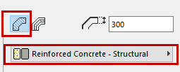
- For a Composite Shell: Use the pop-up to choose its Composite structure.
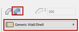 Note: This pop-up lists composites whose “use with” setting includes the shell element: see “Use With” - define composite availability
Shell Thickness: Enter a value for the thickness of the Shell.
If a composite structure is used for the Shell, this field is gray and cannot be modified, as the Shell’s thickness is then determined by the thickness of the Composite as defined in Options > Element Attributes > Composites.
Geometry Method
In Shell Default Settings, click one of the three icons to define the Geometry Method with which to place the new Shell:
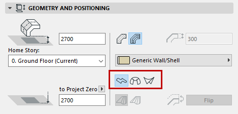
- Extruded
- Revolved
- Ruled
See About Shells for more information.
Morphing Rule (for Ruled Shell only): Click on either the “Smooth” or “Paired” method for defining the geometry of a Ruled Shell, based on how the respective nodes of the two profiles should be connected.
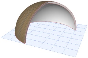
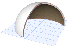
Flip: (Editable in Shell Selection Settings.) The Shell is composed of a membrane and a Shell body attached to one side of the membrane. Use Flip to change sides: The Shell body moves to the other side of Shell membrane.
Shell Special Properties Panel (Extrusion Properties, Revolution Properties)
If you are using either the Extrusion method or Revolved method, this panel contains special properties related to the Shell geometry.
Extrusion Properties
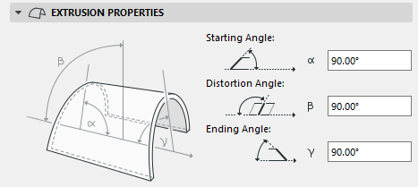
Starting angle: The angle between the plane of the Shell and the Shell edge at the initial point of the extrusion vector.
Distortion angle: Angle of the Shell profile, measured to the Shell plane. By default: 90 degrees, but changing it enables you to extrude the Shell profile at a angle, creating a distorted Shell, provided that either its starting or ending angle is other than 90 degrees.
Ending angle: The angle between the plane of the Shell and the Shell edge at the endpoint of the extrusion vector.
Revolution Properties
For a Revolved Shell:
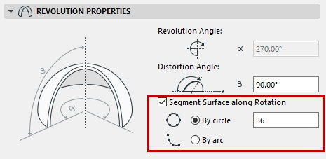
- Revolution angle: Angle of revolution of the Shell around its axis.
- Distortion angle: Angle of the axis of the revolved Shell, measured to the Shell plane angle. Modifying the distortion angle will affect the Shell profile. (Changing the slant angle alone, which is available through graphical editing, will not change the Shell profile, only “tip” it over.)
- Segment Surface Along Rotation
By default, the surface of Revolved Shells is smooth. You have the option of dividing it into segments as needed.
Check the box if you would like to divide the rotated Shell into segmented planes. Next, enter a number for the number of segments.
The given number of segments can be applied to the existing Shell in one of two ways:
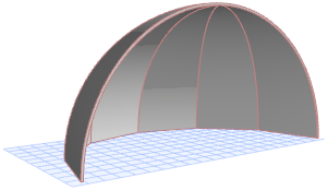
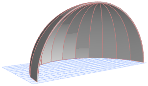
Shell Floor Plan and Section Panel
Cover Fills
See Assign a Cover Fill.
Shell Model Panel
This panel affects the 3D display of the Shell.
See also Override Surfaces With Surface Painter.
For a composite Shell, the “reference side” surface is the first listed skin of the composite, in Composite Settings.
Trimming body: Use this control to define the geometry of the Shell’s trimming body. The trimming body will cut other elements in accordance with this geometry, when you trim another element to this Shell.
- Downward Extrusion
- Upward Extrusion
- EditableNote: To see these trimming bodies while you work (in the 3D window only), turn on Trimming Bodies in the View > On-Screen View Options menu.
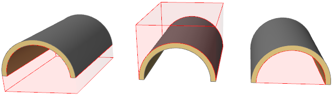
For more information, see Trim Elements to Roof or Shell.