Translators for Export (Detailed Settings)
An IFC Translator for Export defines the rules for handling model elements exported from Archicad to an IFC format.
For an overview of this topic, see IFC Translators: Overview.
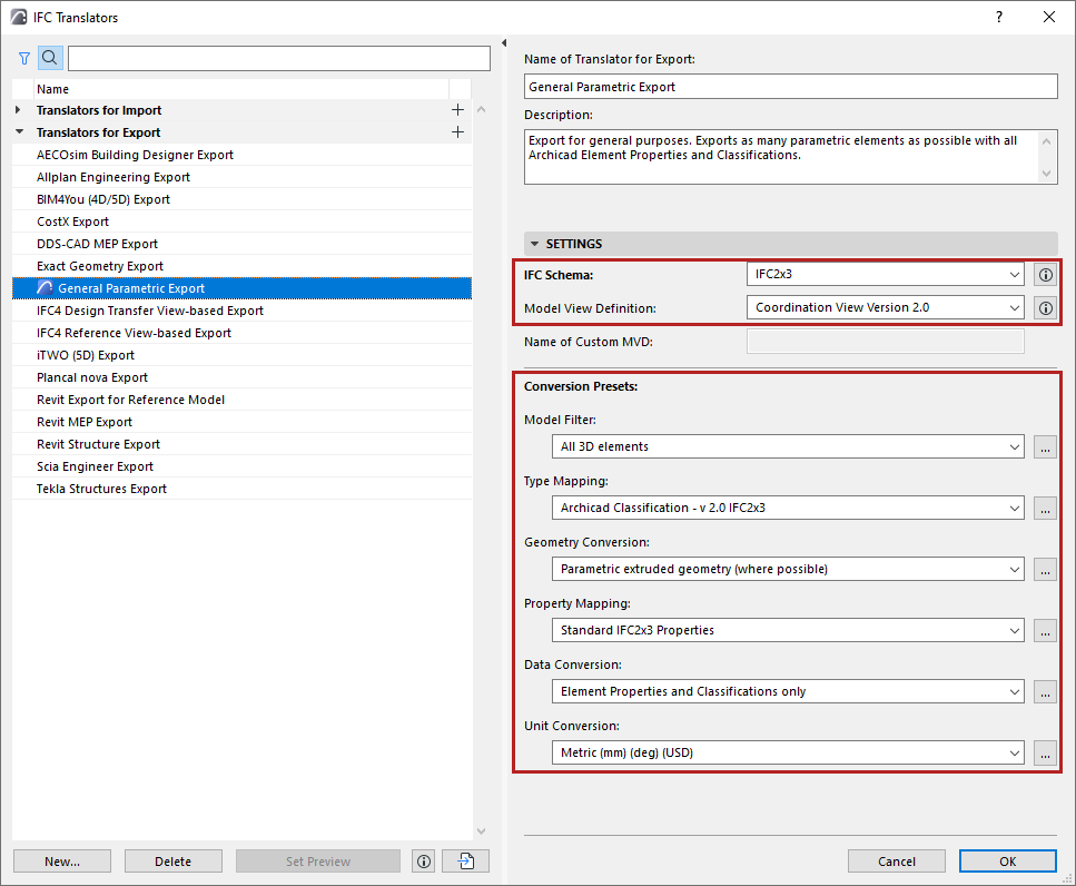
The IFC Translators dialog box (File > Interoperability > IFC > IFC Translators) allows you to view or modify Translator settings, or to create new Translators.
Select a Translator for Export from the list.
The selected Translator’s settings, divided into six Conversion Presets, are shown on the right side.
One of the Translators for Export is the Preview Translator. The Preview Translator exists to provide default mapping definitions needed to work with IFC data in Archicad.
For details, see Preview Translator.
The IFC Schema and Model View Definition categories help in setting up presets that are compatible with particular standards (see details below).

IFC Schema (Translators for Export only)
An IFC Schema is a particular version of the IFC standard. Archicad Translators can support either Schema IFC2x3 (recommended) or IFC4.
Note: IFC2x3 is recommended - this is the most widely used version. Choose IFC4 only if you are certain that it is supported by the application that will receive IFC data using this Translator.
Model View Definition (Translators for Export only)
A Model View Definition (MVD) is a recommendation for which data and elements the IFC model should include, depending on the purpose of the model exchange. If your exported IFC model must conform to a predefined standard MVD, choose that MVD from the list.
Note: Available MVD’s depend upon the IFC Schema chosen above: IFC2x3 or IFC4.
For a more detailed explanation of MVD’s and their characteristics, see Model View Definitions.
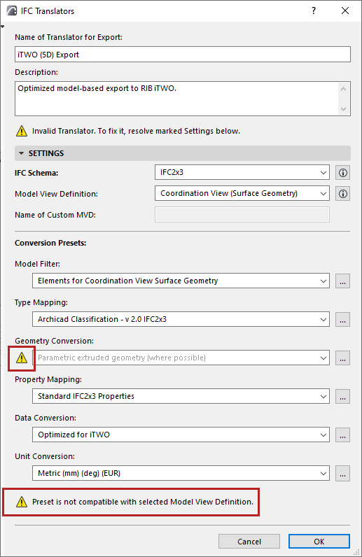
Once you choose an MVD, then certain Translator for Export settings must conform to the requirements of that MVD. If you change a Translator setting so that it no longer conforms to the selected MVD’s requirements, then the Translator becomes invalid, and you get a warning in the dialog box. The problematic setting is also marked:
Working with Conversion Presets
For any category of Conversion Preset, click the dropdown list to view or select a different Preset. The Preset name gives you an idea of how it will affect the exported IFC model, if this Preset is used in a given IFC Translator for Export.
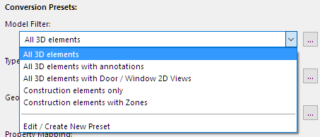
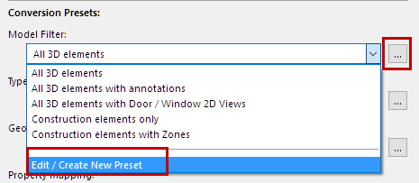
To adjust settings or create a new preset, select Edit/Create New Preset, or click the three buttons at the right of the Preset.
The Preset dialog opens (for example, the Geometry Conversion for IFC Export).
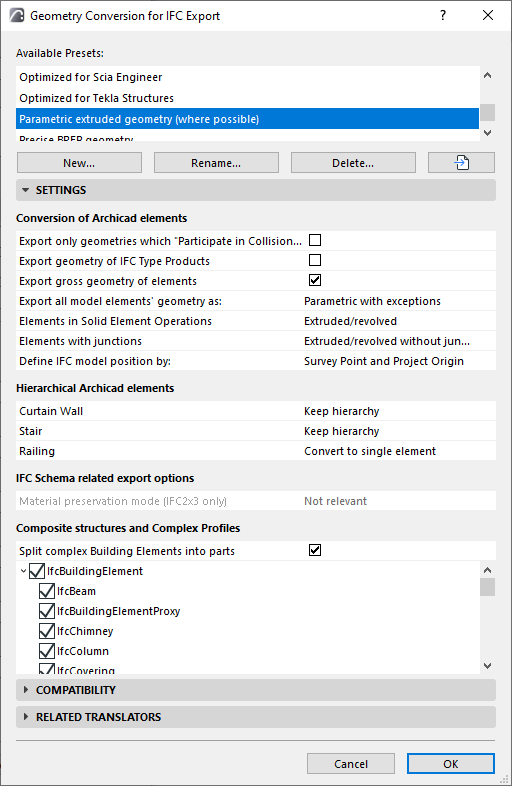
For each of the IFC Export Preset dialogs, view the following:
•Available Presets for this Conversion process (e.g. Geometry Conversion)
•Settings (this is where the export is defined in the greatest detail, for various data types, as defined for the currently selected preset at the top)
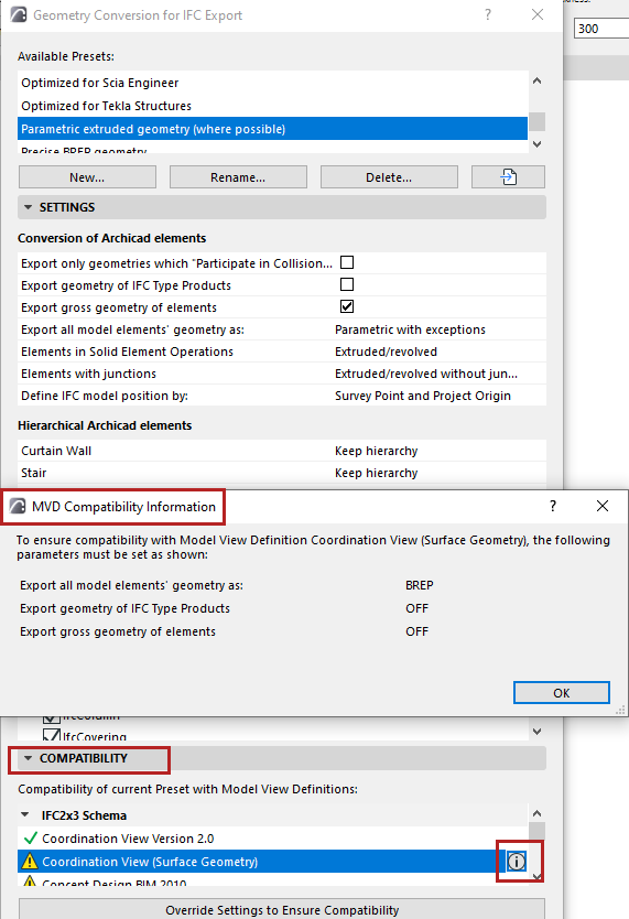
•Compatibility: Feedback on whether the current settings of this preset conform to particular Model View Definitions.
Click the Info button to see the settings conflicts, if any. (If the current Translator for Export does not use that particular MVD, then this conflict need not be a problem.) To ensure compatibility with the MVD, you can adjust the settings as shown in the Info dialog, or just click the Override Settings button to solve the issue.
•Related Translators (all the currently defined IFC Translators for Export which use this Preset)
All Settings of each type of Conversion Preset (used by IFC Translators for Export) are detailed in the following sections.
Geometry Conversion for IFC Export
Property Mapping for IFC Export