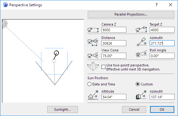
Perspective Projection Settings
Use the View > 3D View Options > 3D Projection Settings command or the 3D Visualization toolbar’s button to open this dialog box.

Use this dialog box to set all the relevant parameters for perspective 3D views, such as viewpoint location and elevation, target location and elevation, width of the viewing cone, and sun position.
Note: Cameras placed in the Floor Plan window also define perspective views, but they are configured in the Camera Tool Settings dialog box, not in this dialog box. To apply the camera-defined view to the 3D model, select the camera and activate the 3D Window.

The preview area on the left side of the dialog box shows your Floor Plan as it currently appears in the window. To see another part of the Project, leave the dialog box, choose another detail using the Navigator or zooming and panning operations, then open it again.
The solid line in the preview area represents the line of vision between the viewpoint and the target point. You can click and drag both the target point and the viewpoint independently of one another. Click anywhere in the preview area and the line of vision will be rotated around the target point to your click position.
The angle defining the View Cone is displayed in the preview area and provides reliable information if the line of vision is horizontal. If the line of vision is looking up or down, the angle can be used only for estimating the resulting view.
After zooms, pans, or numeric distance settings, the viewpoint and/or target point may occasionally disappear from the preview area. To retrieve them, simply Shift-click where you want the viewpoint and Alt/Cmd-click where you want the target point to be in the Window. They will immediately move to the points where you clicked.
You can also specify the following values numerically. Effects of these settings will be displayed graphically in the preview area.
•Camera Z: Enter a value here to specify Camera height from Project Zero. (In this case, the position of the target will remain unchanged.)
•Target Z: Enter a value here to specify Target height from Project Zero.
•Distance: Enter a value here to specify the horizontal distance between Camera and Target.
•Azimuth: Enter a value here to specify Camera Azimuth to Target.
Point Perspectives
•Use Two-Point Perspective: Check this box to view the 3D model from a two-point rather than three-point perspective, while maintaining the original position and viewing angle. This perspective remains until you navigate away.
As a result, all 3D vertical edges become vertical in perspective projection. This emulates the vertical correction function of shift lenses in SLR cameras.
•To get a top view in perspective, set the viewpoint elevation higher than that of the target point elevation, drag the target to the desired location on the plan, then set the distance to zero by dragging the viewpoint until the numeric field displays a minimal value near zero. (You cannot type zero in the Distance field.)
The elevation of the viewpoint and the target point, as well as the View Cone and Roll Angle of the Camera, must be set numerically by using the remaining edit boxes.
View Cone: Enter a value here to specify the opening angle of the Camera View Cone.
Hint: Wider angles (a°=>60°) can fit more objects in the Window, but can also distort the image.
Roll Angle: Enter a value here to specify Camera Roll Angle.
Set Sun Position Graphically
In the preview area, the dashed line with sun icon shows the direction of light for shaded and rendered representations. The sun icon can be dragged around the perimeter of the plan, but it cannot be positioned closer. Its distance is considered to be infinite.
The other controls are identical to those in Parallel Projections.
See Sun Position and Sunlight Settings.