Geometry and Flight Settings (StairMaker)
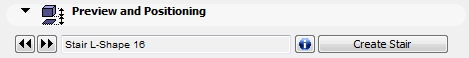
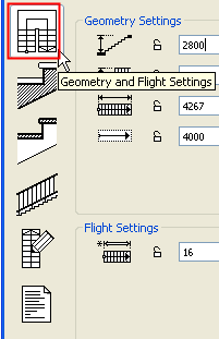
Note: This tab page is part of the StairMaker editing window. To access it, activate the ArchiCAD Stair tool, open Stair Tool Settings, and click the Create Stair or Edit this Stair command. Choose a standard stair type. From the appearing stair editing window, click the Geometry and Flight Settings (top) button from the six buttons at the left.
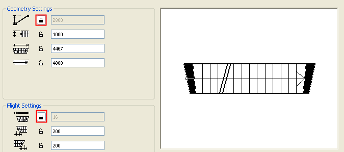
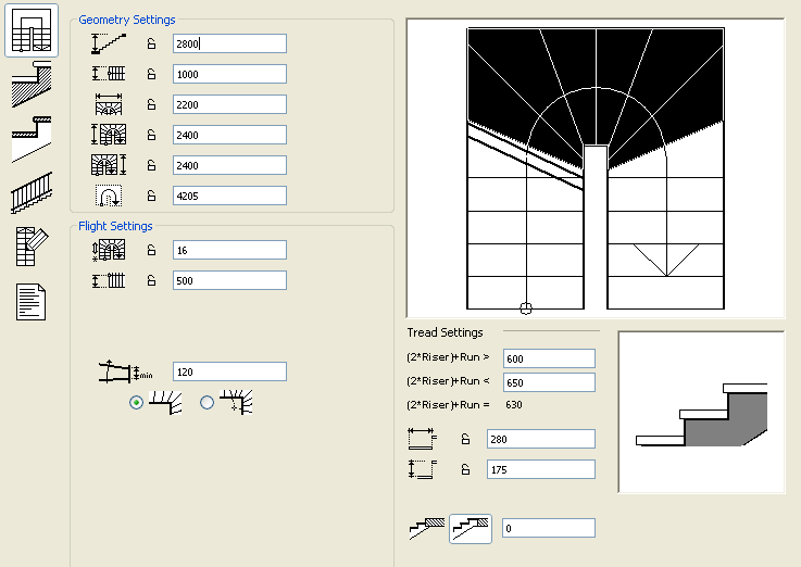
The Geometry and Flight Settings contains preset values for the available parameters and a preview of the floor plan symbol on the right. The changes that you make on the geometry parameters are reflected on this symbol.
Note that several controls on this tab page have lock/unlock icons. You should set the desired geometry and flight settings here, and then lock them. If you do not lock them, modifications on subsequent tab pages may cause StairMaker to automatically recalculate these values. If they are locked, then StairMaker will ensure that subsequent options you set are compatible with this basic geometry.
In the picture below, for example, we have locked the height of the stair at 2800 mm and the number of steps at 16. These will never be changed, no matter what other settings you make on this or the other tab pages.
Set Stair Geometry
On this page, you set the main geometric parameters of the stair: the total height, the horizontal bounding parameters, the flight width, the length, the length of the walking line, as well as the number of risers, the form and the number of the treads in the winder range, the dimensions of the landings, the value of the arrival offset, and the closing angle of the flights. The available fields change according to the type of stair.
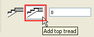
You can add an optional top tread to the stair in the bottom section of this tab page: click the button on the right to add a top tread to the stair at top floor level as shown below.
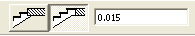
It may either have the same depth as the stair’s other treads, or you can customize the depth of the extra tread by entering a value in the editable field.
If you leave the extra tread depth field’s value at zero, the top tread at floor level will have the same depth as the other treads. To change the top tread’s depth, enter a positive value.
Define Tread Settings
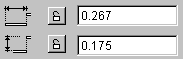
Bottom right in the dialog box, Tread Settings are shown. By setting these parameters, you can define the geometry of the Treads or the angle of the Slope, based on the same geometry. To the right of these fields, the longitudinal section of the stair is shown, giving you instant feedback on your changes.
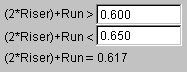
It is easier and more comfortable to climb the stairs if the sum of twice the riser and the run (2*Riser + Run parameter) is within the range of 60 to 63 cm, or 24 to 25 inches. To ensure this condition, you can define a range of values for the (2*Riser) + Run parameter in the Tread Settings section.
The last parameter is not editable. It only shows the current value of the (2*Riser) + Run parameter.
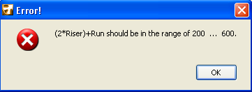
Note: Stair geometry definition is based on the (2*Riser) + Run rule. Every time you modify a parameter, StairMaker checks that the (2*Riser) + Run parameter is still in the appropriate range. In addition to this hierarchy, you may lock one or more parameters by clicking on the lock button. Locked parameters will not be modified. If parameters need changing, StairMaker will skip locked parameters and look for the next value in the hierarchy. If editing is not possible without changing a locked parameter or if too many parameters are locked, an alert will appear.
Break Line in Stair Symbol
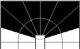
Usually, only the lower part of a stair is displayed in full on the floor plan, on its Home Story. There is a double break line on the 2D Symbol of the stair showing where the stair is cut.
Note: The break line used for GDL Stair symbols is conceptually similar to the Floor Plan Cut Plane used for ArchiCAD construction elements, but the break line is unrelated to the cut plane.
In the Preview picture in the Geometry and Flight Settings editing window, the endpoints of the two break lines can be dragged along the stair outline while the lines remain parallel. If the whole stair will be displayed on the floor plan, moving the break line will have no effect.
Editing the “U-Return Winder” Stair
Some of the available stair types have one or two winders. In the following example using the stair type called “U-Return Winder”, we will see how winders are handled.
Note: Some other Winder-type Stairs available from StairMaker use a different parameter logic.
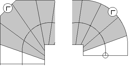
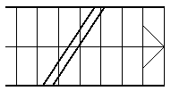
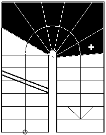
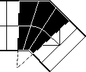
As you can see in the Preview, a part of the stair is highlighted and all treads in the highlighted area are skewed. The highlighted section is the winder range for the stair. If the entire run is highlighted, then all treads are skewed with respect to the line of travel.
Tread edges outside the winder range are perpendicular to the line of travel. (For a comfortable stair, the winder range usually includes at least the entire curved portion of the line of travel, so that non-skewed treads are all in the straight run section.)
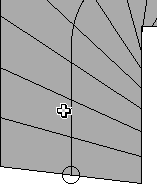
You can change the extent of the winder section with the mouse. First move the pointer onto the stair (the pointer takes a form that may remind you of a spreadsheet editor).
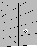
Press and hold the mouse button while moving it along the stair. Some treads turn white as you make the winder section shorter at the end. Release the mouse button, and StairMaker will show the new outline of the stair. Make sure that you define a winder section without overly skewed treads.
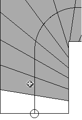
You can see that the treads shown in white are no longer skewed. You can also change the skewed state of a single tread by clicking.
For example, to make the nose of the bottom tread straight, simply click on the second tread. The first tread turns white.
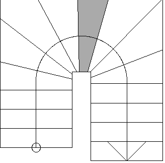
The winder section is “fixed” on the middle tread of the curve, i.e., you cannot shorten either end of the winder range beyond this tread.
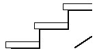
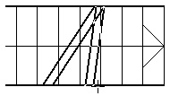
If you shorten both ends of the winder range until the middle tread, you will see something like the illustration.
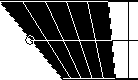
In StairMaker, the tread edges before the beginning and after the end of the winder range are perpendicular to the line of travel. These two edges define a line of travel segment and an inside segment.
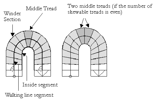
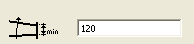
Enter a dimension for the narrowest tread at the stair’s inside segment (“s” in the illustration below) using the parameter field in the Flight Settings section.
StairMaker will divide the stair’s inside segment into treads as shown.
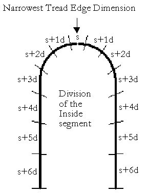
This value will be assigned to the middle tread of the stair run (or to the two middle treads, if the number of treads in the winder range is even).
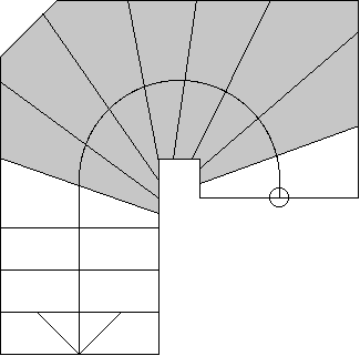
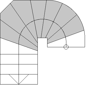
As an alternative to the standard winder, you can create a radial winder. When using this method, the edges of the treads in the winder range meet in a single point. You can select this method by clicking the Radial Winder button.
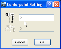
You can change the location of the centerpoint by clicking on it. A dialog box will then prompt you to enter numeric values for the offset.

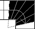
The location and the offset are displayed with dashed lines.
If the corner is chamfered or filleted, the offset is still measured from the imaginary corner. The offset at custom angled stairs looks like this.
If you choose a U-Return Winder stair, StairMaker will automatically set the radial winder midpoint to the midpoint of the arced line of travel.
If you choose a “Straight Run with winder at both ends”, you can define the upper and lower extra length along the side of the stair. The angles of the first and the last edge of the stair depend on this offset.
Note: You cannot define radial winders for this stair type.
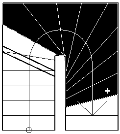
Stair types with winders let you chamfer or fillet the corners of the run. To do this, move the pointer to a corner until it takes the form of a perpendicular sign.
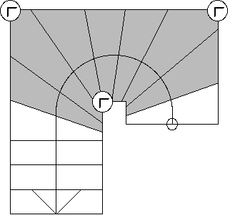
Click on one of the stair’s corner points to open a dialog box offering the three corner shapes available.
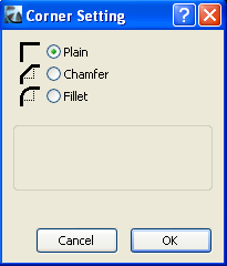
The Plain corner is the “normal” corner shape. When you start editing a new stair, all corners are plain.
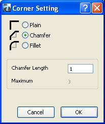
Choose the Chamfer radio button from the dialog box. Editable text fields appear where you can edit the chamfer length. Enter a value and click OK.
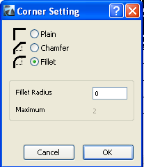
Now fillet the other corner.
You can change the corner shape at any time. If you move the pointer to a chamfered or filleted corner it will again show the perpendicular sign.